Inner diameter measuring device for tubular anastomat

A measuring device and stapler technology, which is applied in the field of medical devices, can solve problems such as data reading trouble, tube drop, movable measuring head moving back, etc., to achieve the effect of convenient inner diameter measurement, convenient operation, and avoiding falling off

Inactive Publication Date: 2021-03-19
CHANGZHOU ANKANG MEDICAL EQUIP
View PDF9 Cites 1 Cited by
  • Summary
  • Abstract
  • Description
  • Claims
  • Application Information

AI Technical Summary

Problems solved by technology

[0003] The existing internal diameter measuring devices for tubular staplers have the following problems during use: 1. The measurement needs to be fixed by pressing the limit position all the time, and when the measurement is released, the movable measuring head moves back, causing measurement trouble;
[0004] 2. It is troublesome to read data by aligning the pointer with the scale, and it is impossible to perform voice broadcast and numerical display, which causes trouble in use;
[0005] 3. The tube at one end cannot be fixed during measurement, and it is easy to cause the tube to fall when operated by a single person, causing trouble in measurement

Method used


Image

  • Inner diameter measuring device for tubular anastomat
  • Inner diameter measuring device for tubular anastomat
  • Inner diameter measuring device for tubular anastomat

Examples


Embodiment 1

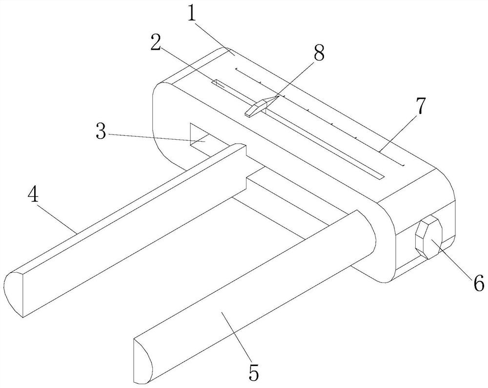
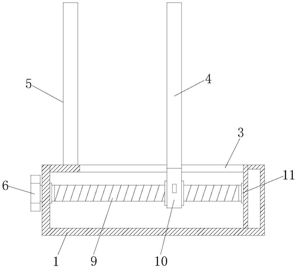
[0028] see Figure 1-6 , the present invention provides the following technical solutions: a tubular stapler internal diameter measuring device, including a base 1, the base 1 inside is provided with a screw 9, the surface of the screw 9 is provided with a sliding seat 10, one end of the sliding seat 10 The movable measuring head 4 is connected, the side of the base 1 is provided with a fixed measuring head 5, the side of the base 1 is provided with an adjusting bolt 6 connected with the screw rod 9, the upper end of the sliding seat 10 is provided with a pointer 8, the base The surface of 1 is provided with a notch 2 corresponding to the position of the pointer 8, the side surface of the base 1 is located on the side of the notch 2, and a scale 7 is provided, and the side of the base 1 is provided with a stop for the movable measuring head 4 to limit sliding. Slide track 3.

[0029] Furthermore, in the present invention, both ends of the screw rod 9 are rotationally connecte...

Embodiment 2

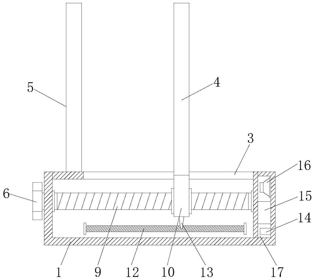
[0032] The difference between this embodiment and Embodiment 1 is that the inside of the base 1 is provided with a sliding resistor 12 on the side away from the sliding track 3, the side of the sliding seat 10 is provided with a connecting contact piece 13, and the inside of the base 1 is far away from the adjustment One side of the bolt 6 is provided with a placement cavity 17, and a storage battery 15 is provided in the middle of the storage cavity 17, a horn 16 is provided on one side of the storage battery 15, and a PLC control module 14 is provided on the other side of the storage battery 15.

[0033] Further in the present invention, a display screen 18 is provided on the surface of the base 1 at the side of the scale 7 .

[0034] Further in the present invention, the sliding resistor 12 , the PLC control module 14 , the speaker 16 and the display screen 18 are all connected to the storage battery 15 .

[0035] Further in the present invention, the connecting contact pie...

Embodiment 3

[0038] This embodiment differs from Embodiments 1 and 2 in that: the base 1 is provided with a fixed plate 19 on the side of the fixed measuring head 5, and the side of the fixed plate 19 close to the fixed measuring head 5 is provided with a pressing plate 21, and the pressing plate 21 and The fixed plates 19 are connected by return springs 20 .

[0039] Further in the present invention, the end of the pressing plate 21 away from the base 1 is arranged in an arc-shaped structure.

[0040] When using this embodiment, the fixed measuring head 5 is inserted into the tubular stapler, and the pressing plate 21 is located on the outer wall of the tube. The elastic force of the return spring 20 makes the pressing plate 21 close to the outer wall of the tube, so that the fixed measuring head 5 cooperates with the pressing plate 21. Realize the clamping and fixing of the tube to avoid falling off due to no hand support during measurement, and then rotate the adjusting bolt 6 to drive ...


PUM


Abstract

The invention discloses an inner diameter measuring device for a tubular anastomat, and belongs to the technical field of medical instruments. The device comprises a base, a screw rod is arranged in the base, a sliding seat is arranged on the surface of the screw rod, a movable measuring head is connected to one end of the sliding seat, and a fixed measuring head is arranged on the side edge of the base. The adjusting bolt rotates to drive the screw rod to rotate, the sliding seat on the surface of the screw rod moves, the movable measuring head on the side edge of the sliding seat slides along the sliding rail to enable the fixed measuring head and the movable measuring head to be tightly attached to the inner wall of a pipe, the base is taken down to observe the position of the pointer on the dial gauge, then the inner diameter value is measured, and inaccurate measurement caused by back movement of the movable measuring head due to finger looseness is avoided; and by adjusting the sliding seat to move, a connecting contact piece is driven to move on the surface of a sliding resistor, the resistance value of the sliding resistor is changed, a corresponding inner diameter value isdisplayed on the display screen according to the change of the resistance value, meanwhile, a loudspeaker carries out voice broadcasting on the value, and inner diameter measurement is facilitated.

Description

technical field [0001] The invention belongs to the technical field of medical instruments, and in particular relates to an inner diameter measuring device for a tubular stapler. Background technique [0002] The stapler is the first stapler in the world. It has been used for gastrointestinal anastomosis for nearly a century. It was not until 1978 that the tubular stapler was widely used in gastrointestinal surgery. It is generally divided into one-time or multiple-use staplers, imported or domestic staplers. It is a device used in medicine to replace traditional manual suturing. Due to the development of modern technology and the improvement of production technology, the clinically used stapler is reliable in quality, easy to use, tight and suitable, especially its fast suturing, easy operation and There are few side effects and surgical complications, and it also enables tumor resection that was unresectable in the past. [0003] The existing internal diameter measuring ...

Claims


Application Information

Patent Timeline
Patent Type & Authority Applications(China)
IPC IPC(8): G01B7/13
CPCG01B7/13
Inventor 王春华李莹李志伟桑小林张玲薛辉蒋易良张佳锴陈政赵红
Owner CHANGZHOU ANKANG MEDICAL EQUIP
Why Eureka
Try Eureka