Cross-laminated-timber shear walls connected in vertical joint through energy-dissipation connecting pieces

A glulam, shear wall technology, applied in the direction of walls, building components, buildings, etc., can solve problems such as the decrease of stiffness and bearing capacity, achieve the limit displacement and energy dissipation capacity improvement, improve energy dissipation capacity, limit displacement increase. Effect

Active Publication Date: 2018-01-09
NANJING UNIV OF TECH
View PDF4 Cites 2 Cited by
  • Summary
  • Abstract
  • Description
  • Claims
  • Application Information

AI Technical Summary

Problems solved by technology

[0004] The purpose of the present invention is to solve the existing cross-laminated timber (CLT) boards connected by nails. After being loaded, the nail connection will be damaged before the fasteners connecting the wall and the ground, resulting in stiffness and load-bearing. To solve the problem of a sharp drop in force, design an orthogonal glulam shear wall connected by energy-dissipating connectors in the vertical joints. By setting multiple energy-dissipating connectors in the vertical joints, the deformation is first concentrated on the energy-dissipating In the parts, the energy dissipation capacity of the system is improved; the stiffness of the system after cracking is changed to a plateau

Method used


Image

  • Cross-laminated-timber shear walls connected in vertical joint through energy-dissipation connecting pieces
  • Cross-laminated-timber shear walls connected in vertical joint through energy-dissipation connecting pieces
  • Cross-laminated-timber shear walls connected in vertical joint through energy-dissipation connecting pieces

Examples


Embodiment 1

[0029] Such as Figure 1-7 shown.

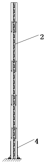
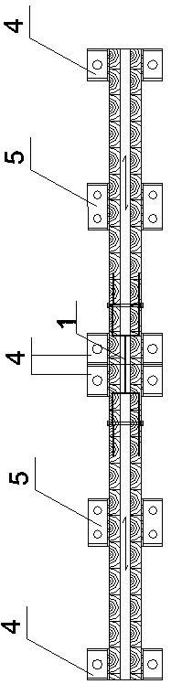
[0030] A cross-laminated timber shear wall connected by energy-dissipating connectors in vertical joints, such as Figures 1 to 3 As shown, it includes multiple energy-dissipating metal connectors 1, the first cross-glued wood shear wall 2, the second cross-glued wood shear wall 3, the first cross-glued wood shear wall 2 and the second cross-glued wood shear wall Two pieces of orthogonal glued wood shear walls 3 are spliced ​​vertically to form vertical joints 6, and the plurality of energy-dissipating metal connectors 1 straddle the vertical joints and simultaneously connect with the first piece of orthogonal glued wood shear walls 2, The second piece of cross-laminated timber shear wall 3 is connected.

[0031] The first piece of cross-glued wood shear wall 2 and the second piece of cross-glued wood shear wall 3 are assembled on the floor or beam through No. 1 metal connector 4 and No. 2 metal connector 5; No. 1 metal connector 4 Set at...


PUM


Abstract

Cross-laminated-timber shear walls connected in a vertical joint through energy-dissipation connecting pieces comprise the first piece of cross-laminated-timber shear wall (2) and the second piece ofcross-laminated-timber shear wall (3). The first piece of cross-laminated-timber shear wall (2) and the second piece of cross-laminated-timber shear wall (3) are vertically spliced, and the vertical joint (6) is formed. The first piece of cross-laminated-timber shear wall (2) and the second piece of cross-laminated-timber shear wall (3) are assembled on a floor through first metal connecting pieces (4) and second metal connecting pieces (5). The cross-laminated-timber shear walls connected in the vertical joint through the energy-dissipation connecting pieces is characterized in that the vertical joint is connected through the multiple energy-dissipation metal connecting pieces (1). A whole-process declining rigidity degeneration mode of the cross-laminated-timber shear walls is promoted into a mode of retaining a rigidity section while the safety and reliability of the cross-laminated-timber shear walls are guaranteed. After energy dissipaters are damaged, the cross-laminated-timber shear walls with the energy dissipaters can continue bearing loads. Compared with a common cross-laminated-timber shear wall, the ultimate displacement of the cross-laminated-timber shear walls is improved by 45%, and accordingly the energy-dissipation capability under the earthquake effect is improved.

Description

technical field [0001] The invention relates to a building structure technology, in particular to a wood structure technology, in particular to a cross-glued wood shear wall connected by energy-dissipating connectors in vertical joints. Background technique [0002] Wooden structures have a history of thousands of years in our country. With the development of science and technology in the construction industry, the technical barriers to the development of wooden structures have been broken, and wooden buildings have become more popular. The wood used in wooden buildings has a high strength-to-weight ratio, and the materials are renewable and environmentally friendly. The assembly rate of wooden structure buildings is high, and the development of wooden buildings meets the assembly and sustainable development requirements of the construction industry. In foreign countries, with the development of medium and high-rise timber structures, cross-laminated-timber (cross-laminated...

Claims


Application Information

Patent Timeline
Patent Type & Authority Applications(China)
IPC IPC(8): E04B2/00E04B1/68E04B1/98E04H9/02
Inventor 刘伟庆徐德良宋佳程陆伟东雷英岳孔周叮
Owner NANJING UNIV OF TECH
Why Eureka
Try Eureka