Wood frame-orthogonal laminated wood shear wall connected by energy-dissipation connector in continuous beams

A technology of glulam and shear wall, which is applied in the direction of building components, building types, buildings, etc., can solve the problems of system stiffness and bearing capacity reduction, and achieve the effect of improving energy consumption capacity and limit displacement

Active Publication Date: 2018-02-13
NANJING UNIV OF TECH
View PDF7 Cites 2 Cited by
  • Summary
  • Abstract
  • Description
  • Claims
  • Application Information

AI Technical Summary

Problems solved by technology

[0004] The purpose of the present invention is to design a method to connect beams through energy-dissipating connectors to solve the problem that the rigidity and bearing capacity of the system drop sharply due to the damage of the conventional connection of coupling beams in wood frame-CLT shear walls. The wooden frame-orthogonal glued wood shear wall, by setting energy-dissipating connectors in the middle of the connecting beams, the deformation is first concentrated in the energy-dissipating parts, and the energy-dissipating capacity of the system is improved; the stiffness of the system after cracking is changed by a steep drop for a plateau

Method used


Image

  • Wood frame-orthogonal laminated wood shear wall connected by energy-dissipation connector in continuous beams
  • Wood frame-orthogonal laminated wood shear wall connected by energy-dissipation connector in continuous beams
  • Wood frame-orthogonal laminated wood shear wall connected by energy-dissipation connector in continuous beams

Examples


Embodiment Construction

[0030] The present invention will be further described below in conjunction with the accompanying drawings and embodiments.

[0031] like Figure 1-9 shown.

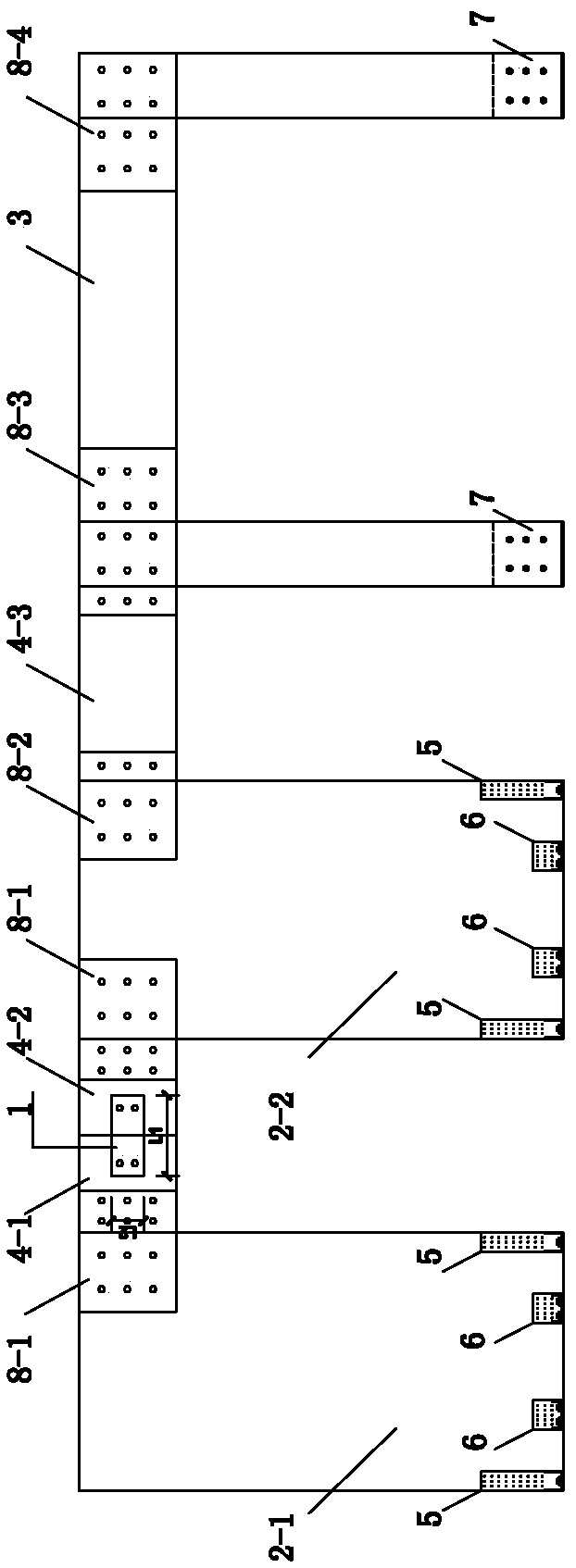
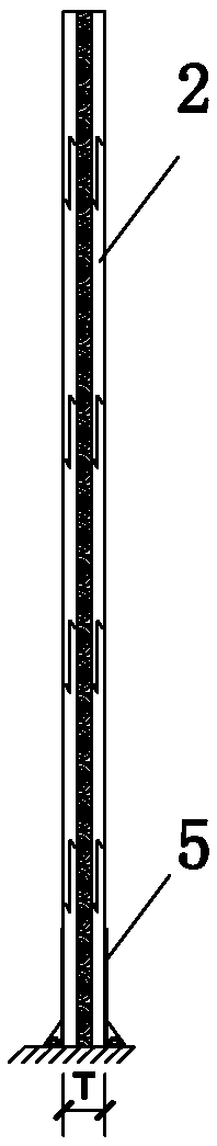
[0032] A wood frame-orthoglued wood shear wall connected by energy-dissipating connectors in the coupling beams, such as Figures 1 to 3 As shown, it includes energy-dissipating metal connector 1, cross-glued wood shear wall 2, glued-laminated wood frame 3, first glued-laminated wood connecting beam 4-1, second glued-laminated wood connecting beam 4-2 and metal connecting piece 5, 6, 7, 8, the connecting beams between the shear walls are spliced ​​vertically to form vertical joints, and the energy-dissipating metal connector 1 straddles the vertical joints and simultaneously connects with the first glulam connecting beam 4-1 and the second Glulam coupling beam 4-2 connection;

[0033] The cross-laminated timber shear walls 2-1 and 2-2, and the glued-laminated timber frame 3 are assembled on beams or floor slabs throug...


PUM


Abstract

The invention discloses a wood frame-orthogonal laminated wood shear wall connected by an energy-dissipation connector in continuous beams. The wood frame-orthogonal laminated wood shear wall comprises orthogonal laminated wood shear wall bodies (2-1 and 2-2) and a laminated wood frame (3) and is characterized in that the first orthogonal laminated wood shear wall body is connected with the firstlaminated wood continuous beam (4-1) through a fourth metal connector (8-1), and the second orthogonal laminated wood shear wall body is connected with the second laminated wood continuous beam (4-2)through another fourth metal connector; the first laminated wood continuous beam and the second laminated wood continuous beam are connected through the energy-dissipation metal connector (1); the second orthogonal laminated wood shear wall body is connected with the laminated wood frame through a fourth metal connector (8-2) and the third laminated wood beam (4-3); one surfaces or two surfaces ofthe orthogonal laminated wood shear wall bodies are fixed to a beam or a floor through first metal connectors (5) and second metal connectors (6); and columns of the laminated wood frame (3) are fixed to the beam or the floor through third metal connectors (7). Limit displacement is increased by 45% while safety and reliability of the laminated wood shear wall bodies are guaranteed, and the energy dissipation capacity under the earthquake effect is improved.

Description

technical field [0001] The invention relates to a building structure technology, in particular to a wood structure technology, in particular to a wood frame-orthoglued wood shear wall connected by energy-dissipating connectors in connecting beams. Background technique [0002] Wooden structures have a history of thousands of years in our country. With the development of science and technology in the construction industry, the technical barriers to the development of wooden structures have been broken, and wooden buildings have become more popular. The wood used in wooden buildings has a high strength-to-weight ratio, and the materials are renewable and environmentally friendly. The assembly rate of wooden structure buildings is high, and the development of wooden buildings meets the assembly and sustainable development requirements of the construction industry. In foreign countries, with the development of medium and high-rise timber structures, cross-laminated-timber (cros...

Claims


Application Information

Patent Timeline
Patent Type & Authority Applications(China)
IPC IPC(8): E04B1/38E04B1/58E04B1/98E04H9/02
CPCE04B1/2604E04B1/38E04H9/021E04B2001/2644E04B2001/2652
Inventor 徐德良刘伟庆居高艳岳孔陆伟东周叮雷英
Owner NANJING UNIV OF TECH
Why Eureka
Try Eureka