Ultrasonic wave flow rate metering device

A flow measurement and ultrasonic technology, applied in measuring devices, measuring flow/mass flow, liquid/fluid solid measurement, etc., can solve problems affecting measurement accuracy, manual hand-holding of gaskets, uncontrollable processing errors, etc., and achieve simple and safe sealing , good waterproof effect, avoiding the effect of high cost

Pending Publication Date: 2017-02-01
DALIAN TAOSONICS INSTR
View PDF6 Cites 5 Cited by
  • Summary
  • Abstract
  • Description
  • Claims
  • Application Information

AI Technical Summary

Problems solved by technology

[0005] The technical problem to be solved by the present invention is that the transducer of the current ultrasonic flow metering device is fixedly installed on the pipe wall outside the flow metering device, which is easily damaged, easily affected by the interference of different factors, the measurement accuracy, the waterproof effect is poor, and it is not beautiful. question
[0006] At the same time, the invention also solves the problem that the installation position of the signal processing device is higher than the flange and is exposed on the outside of the pipeline, which may easily cause accidental contact of the signal processing device; the installation and operation of the ultrasonic transducer is complicated, and the appearance of the signal line transmission pipeline is irregular. It is not conducive to the protection of signal lines; the gasket does not match the ultrasonic flowmeter, the gasket needs to be manually held during installation, the sealing surface of the gasket and the ultrasonic flowmeter is not concentric after installation, and the water flow is disturbed; and the cost of the metal measurement body is high , heavy quality, time-consuming and labor-intensive processing, and uncontrollable processing errors, which affect the accuracy and application of ultrasonic measurement to a certain extent

Method used


Image

  • Ultrasonic wave flow rate metering device
  • Ultrasonic wave flow rate metering device
  • Ultrasonic wave flow rate metering device

Examples


Embodiment Construction

[0033] The present invention is described below in conjunction with accompanying drawing and specific embodiment:

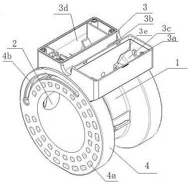
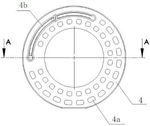
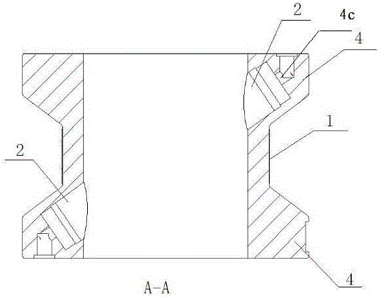
[0034] figure 1 It is an ultrasonic flow metering device of the present invention, which includes a measuring pipe body 1 and a signal processing device 3. Both ends of the measuring pipe body 1 have a boss sealing body 4 matching with the flange of the fluid pipeline to be measured. There are pairs of ultrasonic transducer mounting holes 2 on the inner side of the measuring tube body 1 respectively, and the ultrasonic transducer mounting holes 2 are arranged on the inner side of the measuring tube body 1 and extend to the space of the boss seal 4. Ultrasonic transducers are respectively installed in them, and the opening positions of the ultrasonic transducer installation holes 2 make the measurement signals of the two ultrasonic transducers realize direct radiation, and the measurement signals of the ultrasonic transducers are led to the signal processing devic...


PUM


Abstract

The invention relates to an ultrasonic wave flow rate metering device, which comprises a measuring pipe body and a signal processing device. The ultrasonic wave flow rate metering device is characterized in that a lug boss sealing body matched with a pipeline flange of fluid to be measured is arranged at each of two ends of the measuring pipe body; paired ultrasonic transducer installing holes are formed in the inner side of the measuring pipe body. The ultrasonic transducer installing holes are formed in the inner side of the measuring pipe body, and extend into spaces of the lug boss sealing bodies; the forming positions of the ultrasonic transducer installing holes meet the requirements that the measuring signals of two ultrasonic transducers can realize the direct irradiation; the measuring signals of the ultrasonic transducers are introduced into a signal processing device through a signal wire. The total length of the ultrasonic wave flow rate metering device is smaller than the length of the conventional pipe section type flow rate metering device; the clamping installation is convenient to realize. The two sides of the ultrasonic wave flow rate metering device are connected with a water supply pipe through flanges; then, the signal processing device is positioned in a space formed by the water pipe flanges positioned at the two sides and the measuring pipe body; the position is hidden; the protection on the signal processing device is facilitated. A battery cabin and a main board cabin of the signal processing device use separated design, so that the maintenance is convenient.

Description

technical field [0001] The invention belongs to the field of flow measurement, in particular to an ultrasonic flow measurement device. Background technique [0002] The flow metering device usually includes an ultrasonic transducer and a signal processing device arranged on the measuring body. In the prior art, the ultrasonic transducer is usually fixedly installed on the pipe wall outside the measuring body of the flow metering device, and the emitting surface of the ultrasonic transducer passes through the pipe wall to contact the fluid in the measuring body, and the ultrasonic The transducer signal is transmitted and received to realize the function of measuring fluid. [0003] The signal processing device is generally fixed on the measuring body through a strut, and the signal processing device is higher than the outer diameter of the flange. The ultrasonic transducer is loaded from the outside of the measuring body, sealed and fixed by O-rings and screw parts, and the...

Claims


Application Information

Patent Timeline
Patent Type & Authority Applications(China)
IPC IPC(8): G01F1/66
CPCG01F1/667
Inventor 王国达龚志雄
Owner DALIAN TAOSONICS INSTR
Why Eureka
Try Eureka