Processing box and driving component

A technology for processing boxes and driving heads, applied in the field of electrostatic printing

Pending Publication Date: 2018-01-23
NINESTAR CORP
View PDF7 Cites 0 Cited by
  • Summary
  • Abstract
  • Description
  • Claims
  • Application Information

AI Technical Summary

Problems solved by technology

[0007] The application provides a process box and a drive assembly to solve the problem that when the existing process box contacts and engages with the drive head of the electronic imaging device, the rotational power receiving part of the drive assembly is blocked by the structure in the electronic imaging device and cannot be connected with the drive head. The drive head engages to receive the driving force

Method used


Image

  • Processing box and driving component
  • Processing box and driving component
  • Processing box and driving component

Examples


Embodiment 1

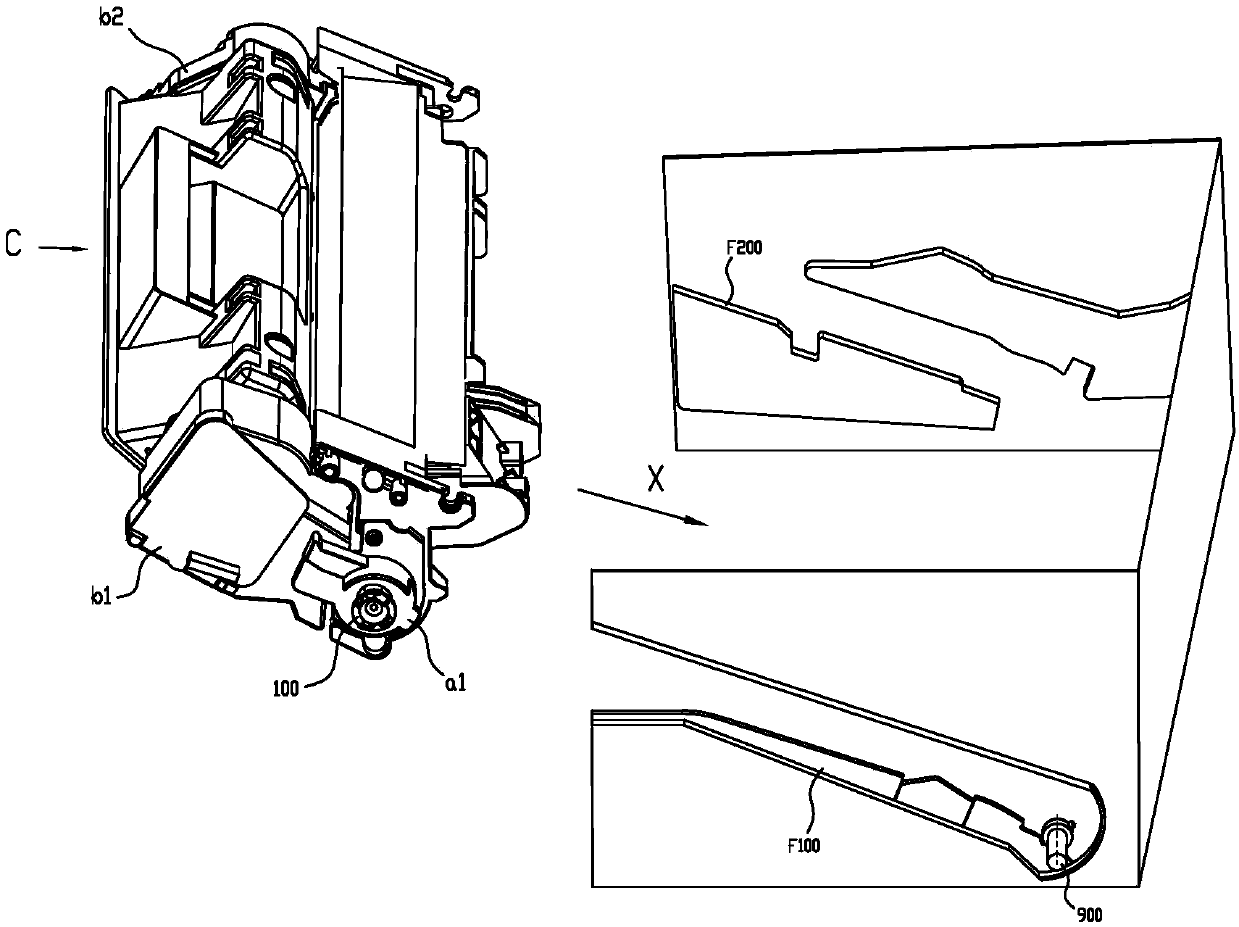
[0100] Such as Figure 6 to Figure 8 As shown, it is a schematic structural view of the process box C1, the process box C1 includes a first shell A and a second shell B, and a first side wall b100 and a second side wall b200 arranged on both sides of the second shell B. The charging element 20 , the cleaning element 40 , the photosensitive element 10 , etc. are accommodated in the first casing A, and the developing element 30 , powder control element 50 , developer, etc. are accommodated in the second casing B.

[0101] (driver components)

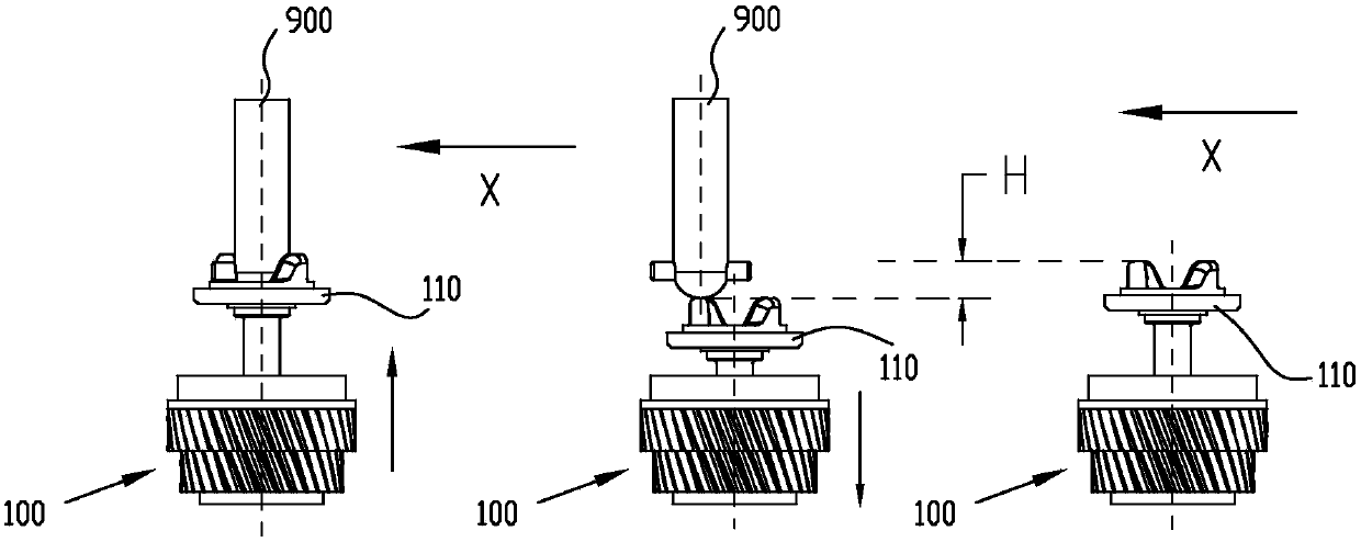
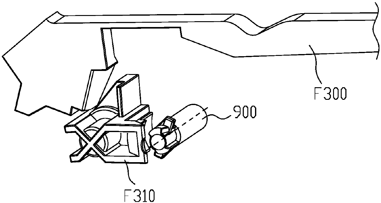
[0102] Such as Figure 7 , Figure 9 As shown, the drive assembly 200, the control mechanism 290 cooperating with the drive assembly 200, and the side plate a100 partially covering the drive assembly 200 are arranged at one end of the process cartridge C1, through the rotational power receiving part 210 of the drive assembly 200 and the electronic imaging device The drive head 900 is engaged to transmit the rotational driving force to the...

Embodiment 2

[0135] Such as Image 6 As shown, it is a schematic structural view of the process box C1, the process box C1 includes a shell (a first shell A and a second shell B) and side walls b100 at both ends of the shell, and a charging element is accommodated in the first shell A 20. The cleaning element 40, the photosensitive element 10, etc., the developing element 30, the powder control element 50, the developer, etc. are accommodated in the second casing B.

[0136] Such as Figure 36 , Figure 37 As shown, the drive assembly 200, the control mechanism 290 cooperating with the drive assembly 200, and the side plate a100 partially covering the drive assembly 200 are arranged at one end of the process cartridge C1, through the rotational power receiving part 210 of the drive assembly 200 and the electronic imaging device The drive head 900 is engaged to transmit the rotational driving force to the process cartridge C1 and drive the rotating components (such as the developing eleme...


PUM


Abstract

The application relates to the technical field of the electrostatic printing, and in particular relates to a processing box and a driving component. The processing box or the driving component is detachably arranged in an electronic imaging device, and comprises a rotary power receiving part and a hub, wherein the rotary power receiving part receives driving force from a driving head of the electronic imaging device and transmits the driving force to the hub, and comprises a power driving part; the power receiving part has a pre-engaging position before receiving the rotary driving force fromthe driving head and a force transmission position when receiving the rotary driving force from the driving head in the electronic imaging device; when the power receiving part is in the pre-engagingposition, the power receiving part is located below the driving head and a rotating shaft of the power receiving part is parallel to and deviated from the rotating shaft of the driving head by observing from the axial direction of the power receiving part, thereby avoiding the structure interference produced between the power receiving part and the driving shaft when performing the contact engaging with the driving head; a technical problem that the rotary power driving part in the driving component cannot engage with the driving head in the electronic imaging device in the prior art is solved.

Description

technical field [0001] The present application relates to the technical field of electrostatic printing, in particular to a process box and a drive assembly. Background technique [0002] In the prior art, the process cartridge is detachably mounted on the electronic image forming apparatus. The electronic imaging device is provided with a driving head for outputting rotational driving force. The process box generally includes a drive assembly that receives the rotational force, a developing element, a developer, a powder control element, and a housing for accommodating the above elements. In addition, according to different types of process box structures, it is additionally provided with a photosensitive element, a charging element, and a cleaning element. elements and stirring elements, etc. The drive assembly of the process box is arranged at one end of the process box along the axial direction of the developing element or the photosensitive element, and then the drivi...

Claims


Application Information

Patent Timeline
IPC IPC(8): G03G21/18
Inventor 梁祺杰曾丽坤
Owner NINESTAR CORP
Why Eureka
Try Eureka