a processing box

A technology of processing box and box body, applied in the field of processing box

Active Publication Date: 2018-05-22
NINESTAR CORP
View PDF7 Cites 0 Cited by
  • Summary
  • Abstract
  • Description
  • Claims
  • Application Information

AI Technical Summary

Problems solved by technology

[0006] The invention provides a processing box and an electronic imaging device, which solves the problem of detecting whether the matching processing box is installed correctly by the electronic imaging device when the processing box is installed in the electronic imaging device

Method used


Image

  • a processing box
  • a processing box
  • a processing box

Examples


Embodiment 1

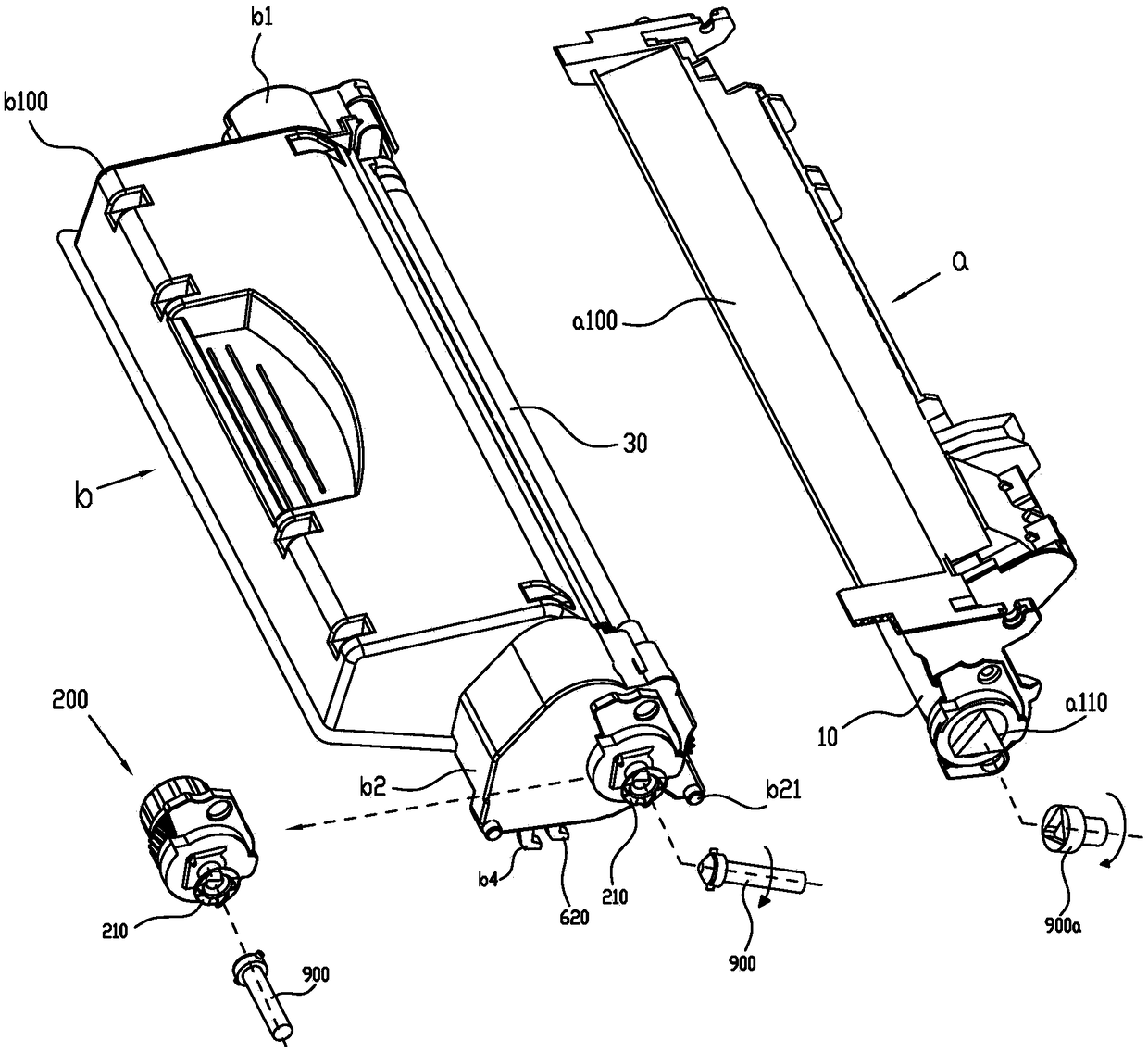
[0107] Such as image 3 As shown, it is a schematic structural diagram of the process box b. The process box b includes a developing chamber b100 and side plates b1 and b2 arranged on both sides of the developing chamber b100. The driving assembly 200 receiving the rotational driving force is installed on the side plate b2. In addition, there is a photosensitive assembly a that cooperates with the process cartridge b to perform developing operations. The photosensitive assembly a includes a photosensitive chamber a100 and a driving member a110 arranged on one side of the photosensitive chamber a100. The driving member a110 and another driving head in the electronic imaging device 900a engages to receive the driving force of rotation and transmit the driving force to the photosensitive unit 10 in the photosensitive chamber a100, and the driving part a110 is preferably a convex triangular structure.

[0108] (process cartridge and photosensitive unit)

[0109] Such as Figure...

Embodiment 2

[0178] The process cartridge b and the photosensitive assembly a which are independent of each other in the above-mentioned embodiment one can also be arranged in a structure connected to each other, such as Figure 45 As shown, the side plates b1 and b2 on both sides are respectively provided with a connecting arm b3a with a hole b3, and a positioning column b22 is provided at the top thereof. The connecting arms b3a of the side plates b1 and b2 extend into the two sides of the photosensitive chamber a100 of the photosensitive assembly a, the upper end of the elastic member a4 abuts against the inner wall of the photosensitive chamber a100, and the lower end of the elastic member a4 is inserted into the positioning column b22 . The process cartridge b and the photosensitive assembly a are connected as a whole through a pair of connecting pieces a3 passing through the positioning holes on both sides of the photosensitive chamber a100 and the hole b3 of the developing chamber b...

Embodiment 3

[0182] In the drive assembly 200 of the above-mentioned embodiment 1 / 2, the matching mechanism (pressing member 220) that can make the power receiving part 210 telescopically engage and disengage with the drive head 900 relative to the hub 270 or the end cover 290 along its rotation axis and slider 230) can also be replaced by the structure of the power receiving part 210 described below and achieve substantially the same effect and function.

[0183] Such as Figure 48 As shown, the claw 211 on the upper end of the power receiving part 210 is set to be tiltable or swingable relative to the main body of the power receiving part 210, that is, the center line of the claw 211 can be inclined at a certain angle relative to the rotation axis of the power receiving part 210, preferably Between 5 ° and 65 °, and the outer surface of the claw 211 is provided with a smooth curved surface transition, and an elastic member 810 (rubber band or extension spring) is also provided on the cla...


PUM


Abstract

The present invention relates to the technical field of electronic imaging, in particular to a process box, which is detachably installed on an electronic imaging device, and a rotatable process box guide rail is arranged on the electronic imaging device, and the process box is installed on the electronic imaging device. On the guide rail of the process box, one side of the process box is provided with a movable positioning column, the positioning column can be supported by the guide rail of the process box, and when the positioning column is moved by an external force, the guide rail of the process box can be rotated , The electronic imaging device is also provided with a detection device equipped with a trigger switch. When the positioning column receives an external force to make the process box guide rail rotate, the process box guide rail touches the trigger switch to make it conduct. After adopting the above-mentioned technical solution, it can be confirmed whether the process cartridge is installed correctly through the conduction state of the detection device.

Description

technical field [0001] The invention relates to the technical field of electronic imaging, in particular to a process box. Background technique [0002] In the prior art, the process cartridge is detachably mounted on the electronic image forming apparatus. The electronic imaging device is provided with a driving head for outputting rotational driving force. The process box generally includes a drive assembly that receives rotational force, a developing unit, a developer, a powder control unit, and a housing for accommodating the above units. In addition, according to different types of process box structures, a photosensitive unit, a charging unit, and a cleaning unit are additionally provided. unit and mixing unit, etc. The drive assembly of the process box is arranged at one end of the process box along the axial direction of the developing unit or the photosensitive unit, and then the driving force of the rotation is transmitted to the process box after the drive assem...

Claims


Application Information

Patent Timeline
Patent Type & Authority Patents(China)
IPC IPC(8): G03G21/18
CPCG03G21/1803G03G21/1842G03G21/1857G03G21/186G03G21/1853G03G15/0865G03G21/1647G03G21/1676
Inventor 丁戈明罗琴马海龙梁祺杰
Owner NINESTAR CORP
Why Eureka
Try Eureka