Driving assembly and processing cartridge adopting same

A technology of drive components and drive components, which is applied in the field of drive components and process boxes, and can solve problems such as the inability to achieve smooth installation of process boxes

Active Publication Date: 2017-06-13
NINESTAR CORP
View PDF7 Cites 4 Cited by
  • Summary
  • Abstract
  • Description
  • Claims
  • Application Information

AI Technical Summary

Problems solved by technology

[0005] The disadvantage of this technical solution is that when the stretching stroke of the power receiving port is limited, it is impossible to completely avoid interference with the drive components through the expansion and contraction of the power receiving port, and the effect of smooth installation of the process box cannot be achieved.

Method used


Image

  • Driving assembly and processing cartridge adopting same
  • Driving assembly and processing cartridge adopting same
  • Driving assembly and processing cartridge adopting same

Examples


Embodiment 1

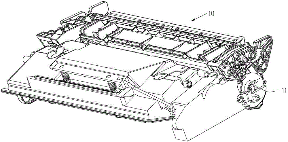
[0190] figure 1 A perspective view of a process cartridge provided in the present application, Figure 10 is the process cartridge, and a power socket 11 for receiving rotational power from an image forming device is disposed at a longitudinal end of the process cartridge 10 .

[0191] The following will introduce in detail how to use the solution of the present application to realize the transmission of power through the control mechanism controlling the engagement of the power socket and the drive mechanism in the image forming device.

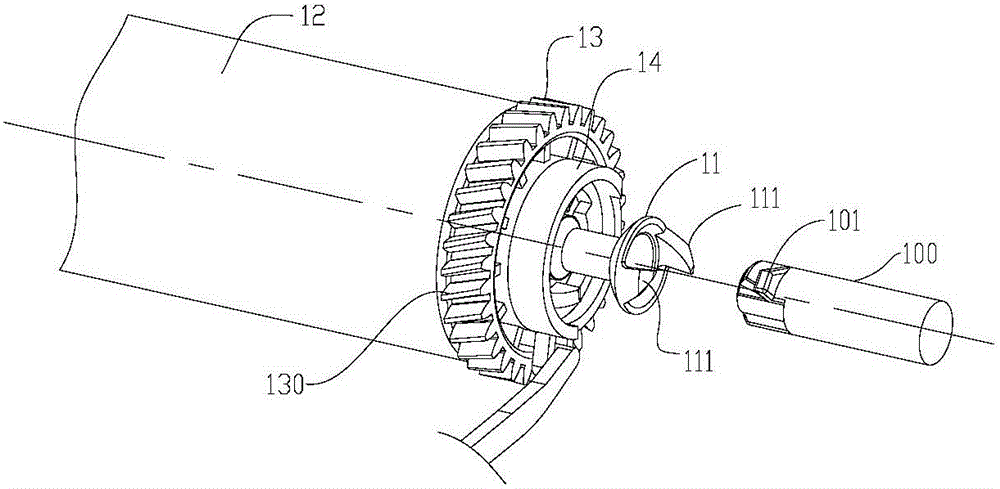
[0192] figure 2 It is a partial structural view of this embodiment. A hub 13 is arranged on the longitudinal end of the process box, and a positioning ring 14 is coaxially arranged on the hub, and the power receiving port 11 is arranged on the hub 13 through the positioning ring 14 . After the process cartridge is installed into the image forming device, the power receiving port 11 is engaged with the driving mechanism 100 in the image for...

Embodiment 2

[0244] Figure 24 Shown is an exploded view of yet another embodiment of the present application.

[0245] The first embodiment provided by the present application is to control the rotation of the hub 13 through the control mechanism, so as to drive the rotation of the power socket 11 .

[0246] However, in the embodiment provided by this embodiment, the power receiving port 011 is controlled to rotate by the control mechanism during the process of installing the process cartridge. During this process, the power receiving port 011 rotates relative to the hub 013 .

[0247] like Figure 24 As shown, the control mechanism includes a positioning ring 014, a first guide sleeve 015A, a second guide sleeve 015B, and an intermediate connecting part 016; the positioning ring 014 is also provided with an adjustment part 0142.

[0248] The power receiving port 011 passes through the positioning ring 014, the first guide sleeve 015A, and the second guide sleeve 015B are arranged on th...

Embodiment 3

[0255] Figure 27 It is another embodiment of the present application. The present application also provides a solution, that is, only the control mechanism is required to control the rotation of the power socket 11 to avoid interference between the process cartridge and the drive mechanism of the image forming device during installation. That is to say, the control mechanism of the first embodiment does not include the guide sleeve 15, that is, when the positioning ring rotates, the power receiving port 11 does not slide along the direction of its rotation axis, and the control mechanism is also used to control the power receiving port 11. to rotate.

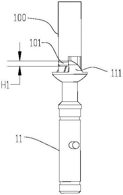
[0256] In this embodiment, the end of the claw 111 of the power receiving port 11 is set to be an inclined surface or a curved surface; when the process is installed along the X direction, the claw of the power receiving port 11 The end 1111 of 111 is in contact with the protruding part 101 of the driving mechanism 100, and t...


PUM


Abstract

The invention relates to the technical field of static printing, particularly to a driving assembly and a processing cartridge adopting the same. The driving assembly is detachably mounted in an image formation apparatus to receive driving force; the driving assembly comprises a power receiving port and a hub; the power receiving port receives the driving force from the image formation apparatus and transfers the driving force to the hub; and the image formation apparatus processing cartridge comprises the driving assembly. The processing cartridge provided by the invention rotates by controlling the power receiving port, and then enables the power receiving port to rotate to a preset position, so that interference generated in mounting the driving assembly or the processing cartridge into the image formation apparatus can be avoided effectively.

Description

technical field [0001] The present application relates to the field of electrostatic printing technology, in particular to a drive assembly and a process box using the assembly. Background technique [0002] This application relates to a process box, which is applied to an image forming device based on electrostatic printing technology, and the image forming device can be any one of laser image forming device, LED image forming device, copier, and facsimile machine . [0003] The process cartridge is detachably installed in the image forming apparatus. A plurality of rotating parts are arranged in parallel on the length direction of the process box, and the rotating parts include a photosensitive element with a photosensitive layer for receiving the laser beam irradiation in the image forming device to form an electrostatic latent image, and a photosensitive element for charging the surface of the photosensitive element. Thereby, the charging member for forming uniform cha...

Claims


Application Information

Patent Timeline
IPC IPC(8): G03G21/18
CPCG03G21/186
Inventor 罗琴马海龙刘金莲曹辉吴连俊陈德曹建新
Owner NINESTAR CORP
Why Eureka
Try Eureka