Rotary supporting frame for displayer

A display and support frame technology, which is applied in the direction of the machine platform/stand, support machine, pivot connection, etc., and can solve the problems of the hanger swinging down and the load bearing of the hanger is small

Pending Publication Date: 2018-01-26
ZHEJIANG JUYOU INTELLIGENT TECH CO LTD
View PDF11 Cites 4 Cited by
  • Summary
  • Abstract
  • Description
  • Claims
  • Application Information

AI Technical Summary

Problems solved by technology

[0002] In order to meet the user's needs for learning and working in many aspects such as display reading, there are many kinds of movable supports for placing displays on the existing market, especially the gas spring rotating supports with multi-angle adjustment, and there are also some mechanical ones. The movable support of this kind of display usually includes a clamping seat, which is used for fixing on the target object, such as a table, a bed frame, etc., and the rotating support on the said clamping seat The arm is used for multi-angle adjustment. The support arm is connected with a hanger for installing the display. The more complicated point is to set the support arm into a multi-section type to achieve more adjustments.
[0003] Since the hanger is used to install the monitor, the hanger needs to bear a relatively large load. If there is a vertical rotation between the hanger and the support arm, it is easy to cause the hanger to swing downward under the load. Therefore, the existing The hanger has the problem of bearing a small load

Method used


Image

  • Rotary supporting frame for displayer
  • Rotary supporting frame for displayer
  • Rotary supporting frame for displayer

Examples


Embodiment 1

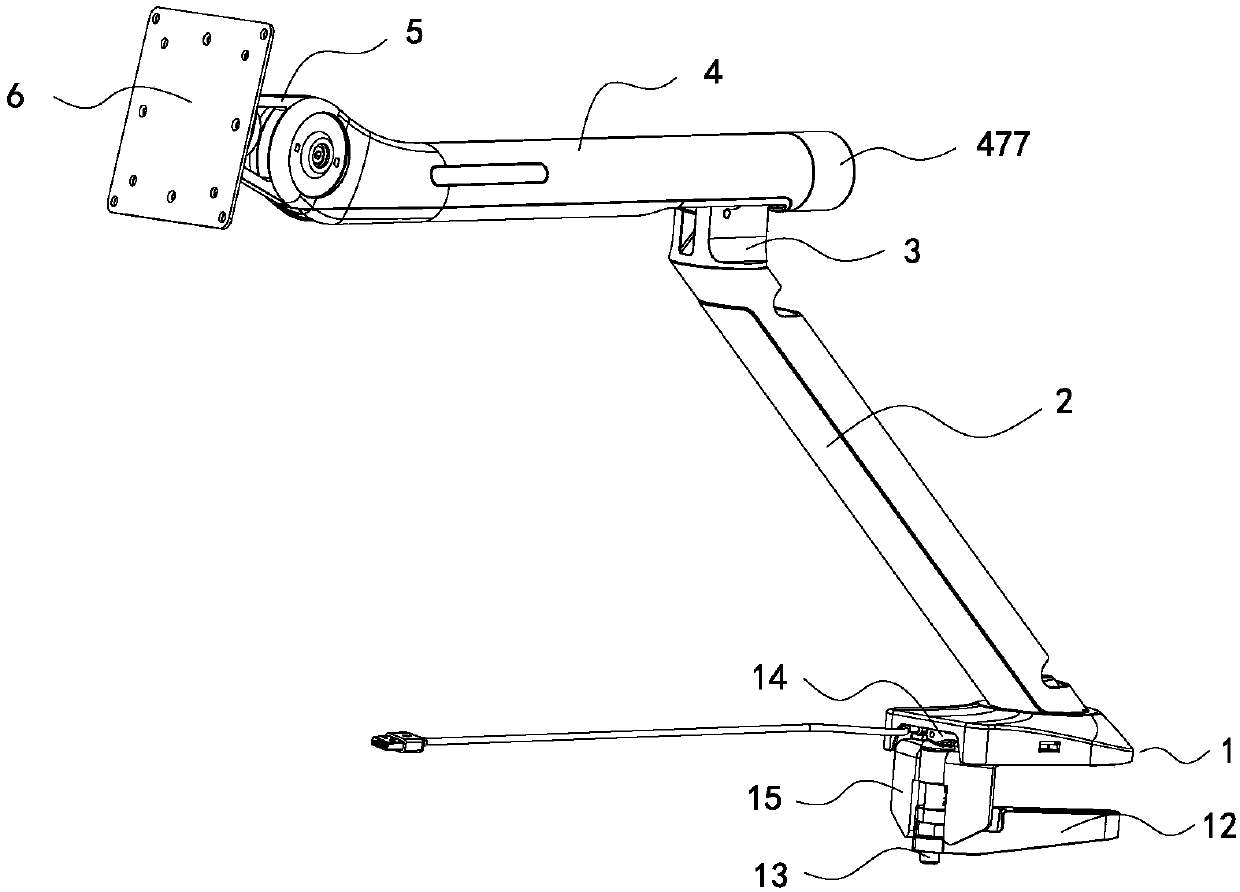
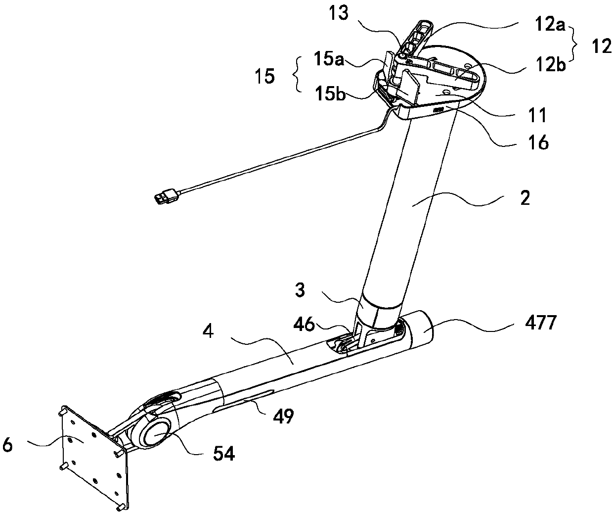
[0030] Such as Figure 1 to Figure 2 As shown, a display rotating support frame shown in this embodiment includes a clamping seat 1 for fixing on an object, a support arm is rotatably connected to the clamping seat 1, and a support arm is connected to the support arm for The hanger 6 of display is installed, and in the present embodiment, support arm preferably comprises upper support arm 4 and lower support arm 2, and the lower end of lower support arm 2 is rotationally connected with clamping seat 1, and one end of upper support arm 4 is used for connecting with lower support arm. The arm 2 is rotatably connected, and the other end is rotatably connected with the hanger 6 .

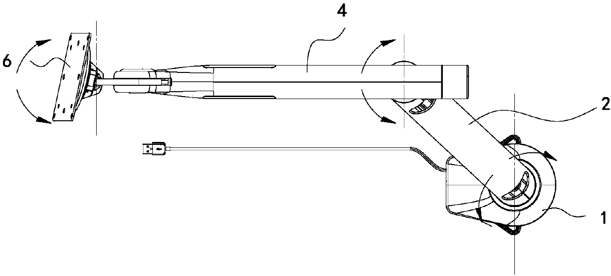
[0031] For specific rotation methods, see image 3 and Figure 4 As shown, the relative rotation between the clamping seat 1 and the lower support arm 2 is a horizontal rotation, and the rotation range is preferably between 0° and 180°, and the relative rotation between the lower support arm 2 and the...

Embodiment 2

[0059]The difference between this embodiment and Embodiment 1 is that in this embodiment, the first clamping plate and the second clamping plate are separately and separately rotatably connected to the locking shaft, that is, both the first clamping plate and the second clamping plate They can be opened or closed with each other. Using this structural design, the clamping plate can be used for more targets. When the target is small, the gap between the first clamping plate and the second clamping plate can be The included angle is reduced. When the target object is large, the included angle between the first clamping plate and the second clamping plate can be increased to increase the clamping force area and make the clamping more stable.

[0060] In this embodiment, as a preference, the included angle between the first limiting plate and the second limiting plate is less than 180°. This design can prevent the first clamping plate and the second clamping plate from being in a s...


PUM


Abstract

The invention discloses a rotary supporting frame for a displayer and belongs to the field of displayer auxiliary connection fittings. The rotary supporting frame comprises a clamping seat for being fixed to a target object, and supporting arms are rotationally connected to the clamping seat; a hanger for installing the displayer is connected to the upper supporting arm; a rocker arm disc frame isconnected between the upper supporting arm and the hanger and rotationally installed on the upper supporting arm; and a friction plate is further arranged inside the upper supporting arm and keeps making contact with the surface of the rocker arm disc frame. The rotary supporting frame has the advantage that the load bearing capacity of the hanger can be improved.

Description

【Technical field】 [0001] The invention relates to a display rotating support frame, which belongs to the field of display auxiliary connection accessories. 【Background technique】 [0002] In order to meet the user's needs for learning and working in many aspects such as display reading, there are many kinds of movable supports for placing displays on the existing market, especially the gas spring rotating supports with multi-angle adjustment, and there are also some mechanical ones. The movable support of this kind of display usually includes a clamping seat, which is used for fixing on the target object, such as a table, a bed frame, etc., and the rotating support on the said clamping seat The arm is used for multi-angle adjustment. The support arm is connected with a hanger for installing the display. The more complicated point is to set the support arm into a multi-section type to achieve more azimuth adjustments. [0003] Since the hanger is used to install the monitor,...

Claims


Application Information

Patent Timeline
Patent Type & Authority Applications(China)
IPC IPC(8): F16M11/20F16M11/12F16C11/10
Inventor 黄志优游说吴刚
Owner ZHEJIANG JUYOU INTELLIGENT TECH CO LTD
Why Eureka
Try Eureka