Version displaying system and method based on CPLD_FPGA (Complex Programmable Logic Device_Field Programmable Gate Array)

A display method and display system technology, which is applied in the direction of version control, software maintenance/management, etc., can solve the problems of disallowance, etc., and achieve the effect of reducing hardware cost and increasing portability

Inactive Publication Date: 2018-01-26
ZHENGZHOU YUNHAI INFORMATION TECH CO LTD
View PDF3 Cites 1 Cited by
  • Summary
  • Abstract
  • Description
  • Claims
  • Application Information

AI Technical Summary

Benefits of technology

The technical feature described in this patented technology allows for concurrent displaying both stages (stage numbers) and non-additive data from two separate devices - one device called PLD or FPGA chip. This means fewer components are needed compared to previous versions used only once. Additionally, when there're multiple types of light sources available, they don’ll have more flexibility than traditional methods like LCD displays due to their ability to adjust brightness levels accordingly.

Problems solved by technology

The technical problem addressed by this patented technology relates to improving the efficiency and flexibility of controlling electronic devices like servers with displays based solely upon their capabilities.

Method used


Image

  • Version displaying system and method based on CPLD_FPGA (Complex Programmable Logic Device_Field Programmable Gate Array)

Examples


Embodiment 1

[0036] This embodiment proposes a version display method based on CPLD_FPGA, which is designed by Verilog hardware description language and instantiated at the top layer of the code, and the LED number parameter and stage version input information are given according to actual needs; the LED control signal output by CPLD / FPGA Connect to the cathode of the LED, connect the anode of the LED to Vcc, and control the on and off of the LED.

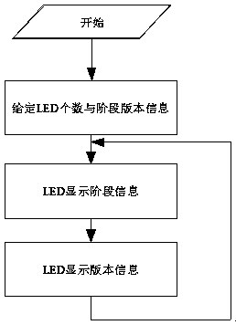
[0037] The version display method based on CPLD_FPGA, as attached figure 1 As shown, the specific implementation process includes:

[0038] Step 1, given the number of LEDs and stage version information;

[0039] Step 2, LED time-sharing display stage version information;

[0040] Specifically, the stage and version information are displayed in time-sharing through the FSM, which solves the contradiction that the simultaneous display of stage and version information requires a large number of LEDs, increases hardware costs and PCB area, and d...

Embodiment 2

[0050] A version display method based on CPLD_FPGA proposed in this embodiment, on the basis of Embodiment 1, adds a specific technology of LED time-sharing display stage version information, and a specific technology of using a parameterized method for the number of LEDs, The specific implementation technical content of the version display method is further improved, making it more practical and practicable.

[0051] The version display method based on CPLD_FPGA described in this embodiment, the specific implementation process includes:

[0052] Step 1, given the number of LEDs and stage version information;

[0053] Step 2, LED time-sharing display stage version information;

[0054] Specifically, FSM design is adopted, that is, the first state is idle state, and then after a period of time (such as 1s), it will automatically jump into the stage display state, and after a period of time (such as 1s), all LEDs will turn off and jump to the next one. state, and finally enter...

Embodiment 3

[0066] A kind of version display method based on CPLD_FPGA that this embodiment proposes, on the basis of embodiment 2, has increased the step to the version display verification based on CPLD_FPGA, can verify the correctness of this version display method, specific process is as follows:

[0067] The function simulation is carried out through ModelSim; for example, the number of LEDs is set to 4, the stage information is 0011, and the version information is 0101. The meaning of the specific value is defined by the architect; the simulation result is: the LED control signal is in the stage information and version information Inter-cycle, that is, cycle between different values ​​​​from 0011-0101-0000, and the cycle of each stage can be defined by itself, such as 1s. Through the above verification process, it can be shown that the version display method adopts LEDs to alternately display stage version information without adding additional hardware structures and reduces hardware...


PUM


Abstract

The invention discloses a version displaying method based on a CPLD_FPGA (Complex Programmable Logic Device_Field Programmable Gate Array), and relates to the technical field of the server CPLD/FPGA.Design is carried out through a Verilog hardware description language, instantiation is carried out on a code top layer, and an LED (Light Emitting Diode) number parameter and stage version input information are given according to practical requirements; an LED control signal output by the CPLD/FPGA is connected to the LED to control the LED to be turned on and off; specifically, through an FSM (Finite State Machine), the LED is designed to carry out the time sharing display of stage version information; the LED number declares an input/ output port through a parameterization way, codes do notneed to be revised when LED number requirements are different in different designs, but an application can be directly instantiated. By use of the method, on a premise that no additional LEDs and CPLD/FPGA chips are added, stage information and version information can be simultaneously displayed, and hardware cost is lowered; and meanwhile, a transplantation problem brought by different LED numbers is solved, and code transplantation ability is increased.

Description


Claims


Application Information

Patent Timeline
Owner ZHENGZHOU YUNHAI INFORMATION TECH CO LTD
Why Eureka
Try Eureka