Auxiliary platform of ophthalmic equipment

An auxiliary platform and equipment technology, applied in the field of medical devices, can solve the problems that affect the inspection effect, affect the inspection efficiency, patients do not know the medical inspectors, etc., and achieve the effect of ingenious structure, convenient use, and different heights and angles.

Inactive Publication Date: 2018-01-30
肖云兰
View PDF6 Cites 0 Cited by
  • Summary
  • Abstract
  • Description
  • Claims
  • Application Information

AI Technical Summary

Problems solved by technology

[0002] In the current eye hospital, the frequency of ophthalmic diseases is getting higher and higher. At the same time, due to the importance of the eyes, when the eyes are checked, sometimes different patients are usually involved. , different postures such as sitting, lying, and standing are very common. At the same time, due to the different heights of patients, when using the instrument for adjustment, sometimes it is necessary to adjust the position of the instrument for different patients at any time to achieve the best examination and treatment. effect; but the existing ophthalmic instruments are generally fixed and cannot be rotated when they leave the factory. However, when the patient is subjected to ophthalmic examination, the patient's inspection angle often needs to be adjusted, and if the patient is allowed to adjust the sitting posture, then, It is easy to cause patients not to know the intention of the medical examiners, and often requires long-term communication, which not only affects the efficiency of the examination, but also affects the effect of the examination. Therefore, it is necessary to improve the design of the supporting device of the ophthalmic instrument in order to improve the effect of the ophthalmic examination

Method used


Image

  • Auxiliary platform of ophthalmic equipment
  • Auxiliary platform of ophthalmic equipment
  • Auxiliary platform of ophthalmic equipment

Examples


Embodiment Construction

[0019] The specific implementation manners of the present invention will be described in further detail below in conjunction with the accompanying drawings.

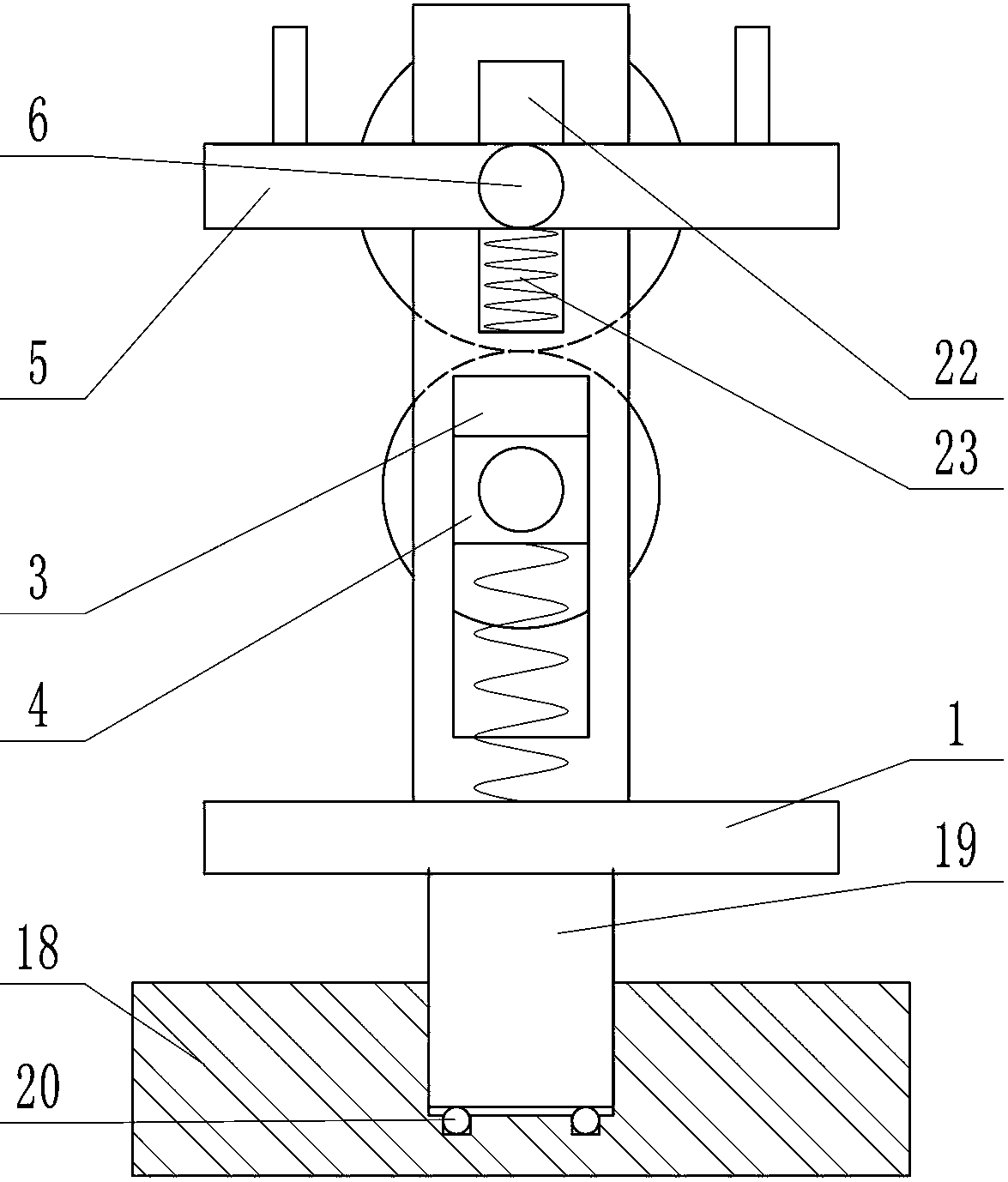
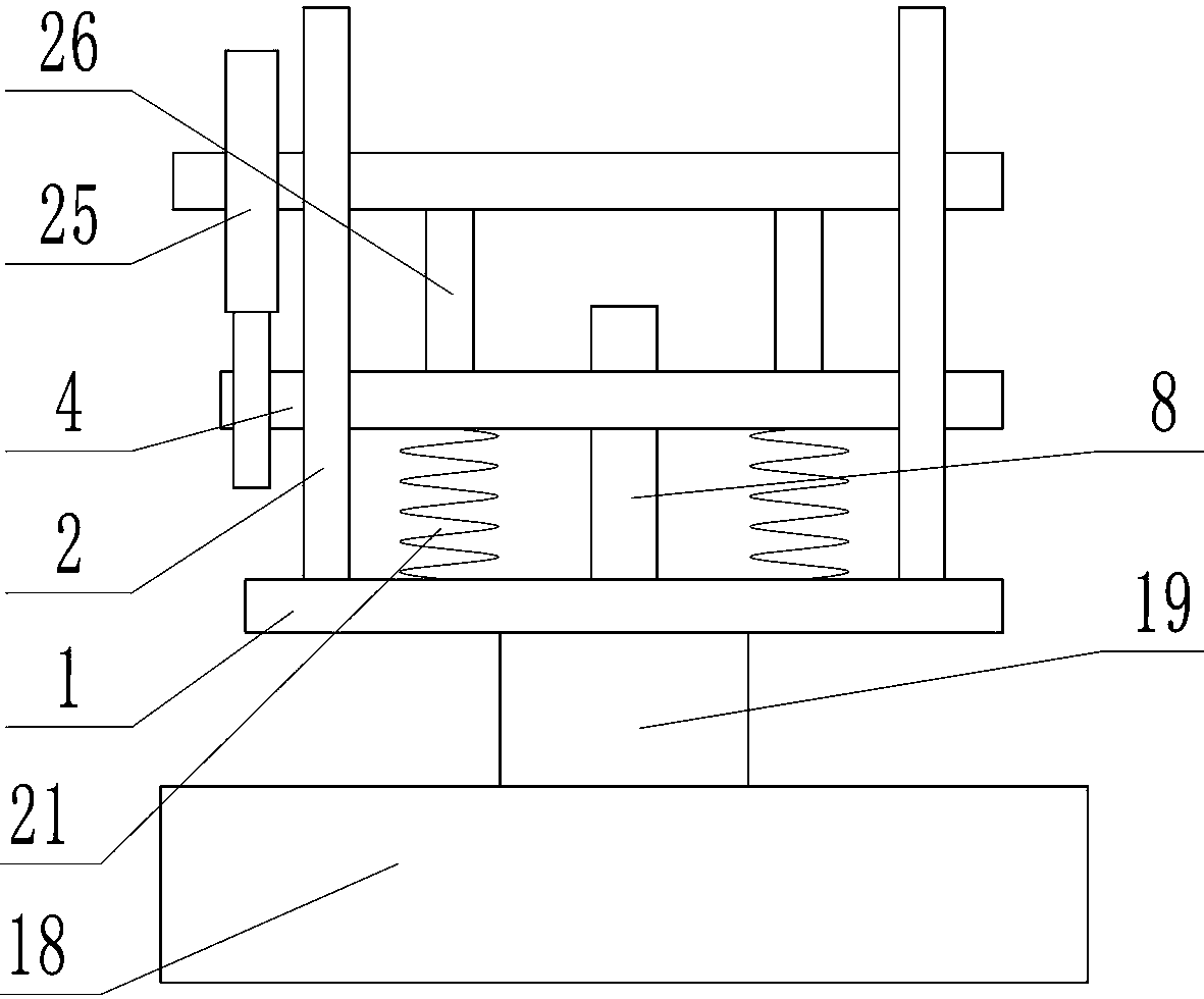
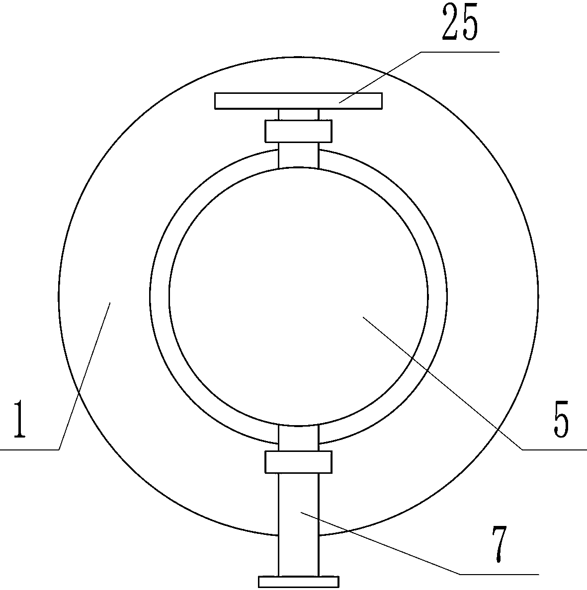
[0020] Depend on Figure 1-10 It can be seen that the present invention includes a horizontally placed fixed plate 1, two vertically placed and symmetrically arranged support plates 2 are fixed above the fixed plate 1, each support plate 2 is provided with a vertical groove 3, and the vertical groove 3 is installed with a first slider 4 that can move up and down. The movable plate 5 that moves up and down, the center of the movable plate 5 is provided with a rotating shaft 6 that runs through the two support plates 2, the movable plate 5 can swing in the vertical plane with the rotating shaft 6, and the center of the first slider 4 is provided with a front end The open cavity is provided with a movable and rotatable adjustment rod 7 in the cavity, and the front end of the adjustment rod 7 is placed outside the first sli...


PUM


Abstract

Disclosed is an auxiliary platform of ophthalmic equipment. The auxiliary platform can well achieve the function of being adjusted conveniently according to the demands of different patients; the auxiliary platform comprises a fixing plate, the fixing plate is fixedly provided with two support plates, a first sliding block and a movable plate capable of swinging in a vertical plane are installed on each support plate, and an adjusting rod is arranged in the centers of the first sliding blocks; a cam and a rotating wheel are fixedly arranged in one first sliding block, the rotating wheel is fixedly provided with a first gear, a second gear meshed with the first gear is installed on a rotating shaft, through holes are formed in the rotating wheel and the cam, the external circle of the adjustment rod is provided with a clamping unit, the adjustment rod can rotate to drive the cam and the rotating wheel to rotate through the clamping unit, the forth-back movement of the adjusting rod canmake the clamping unit alternately clamped in the through holes of the cam and the rotating wheel, each first sliding block is internally provided with a locating device formed by an annular groove, an elastic clamping block and a baffle, the elastic clamping blocks can be clamped in arc grooves, and annular pressing plates can be extruded by the baffles to be detached from the elastic clamping blocks; the auxiliary platform of the ophthalmic equipment is ingenious in structure and convenient to use.

Description

technical field [0001] The invention relates to the technical field of medical equipment, in particular to an ophthalmic equipment auxiliary platform. Background technique [0002] In the current eye hospital, the frequency of ophthalmic diseases is getting higher and higher. At the same time, due to the importance of the eyes, when the eyes are checked, sometimes different patients are usually involved. , different postures such as sitting, lying, and standing are very common. At the same time, due to the different heights of patients, when using the instrument for adjustment, sometimes it is necessary to adjust the position of the instrument at any time for different patients to achieve the best examination and treatment. effect; but the existing ophthalmic instruments are generally fixed and cannot be rotated when they leave the factory. However, when the patient is subjected to an ophthalmic examination, it is often necessary to adjust the patient's inspection angle, and...

Claims


Application Information

Patent Timeline
Patent Type & Authority Applications(China)
IPC IPC(8): A61B50/24A61B50/26
Inventor 刁婷婷
Owner 肖云兰
Why Eureka
Try Eureka