
Intelligent extraction equipment

An extraction equipment and extraction technology, which are applied in liquid solution solvent extraction and other directions, can solve the problems of difficulty in strengthening layered liquid, low accuracy of manual operation, and influence on the purity of lower layer liquid, etc., and achieve the effect of high accuracy and simple method.

Active Publication Date: 2018-02-09
安徽恒达药业有限公司
View PDF6 Cites 6 Cited by
  • Summary
  • Abstract
  • Description
  • Claims
  • Application Information

AI Technical Summary

Problems solved by technology

When the existing extraction and separation device obtains the extraction stratified liquid, the liquid pipe and the liquid valve installed at the bottom of the extraction and separation device are mostly used for separation and acquisition. In this way, the upper liquid will drop with the outflow of the lower liquid and be separated from the extraction. The lower liquid attached to the inner wall of the device is confused, and at the same time, if you do not pay attention, the mixed layer will flow out with the lower liquid, thereby affecting the purity of the lower liquid; moreover, by using additional auxiliary tools to absorb the upper liquid and the mixed layer, To obtain the lower layer liquid, this method requires additional tools, which increases the difficulty of obtaining the layered liquid to a certain extent; in addition, the entire process of obtaining the layered liquid requires manual operation, but the accuracy of manual operation is not high, and it is slightly If you don't pay attention, two layers of layered liquid will be taken out at the same time.

Method used


Image

  • Intelligent extraction equipment

Examples


Embodiment Construction

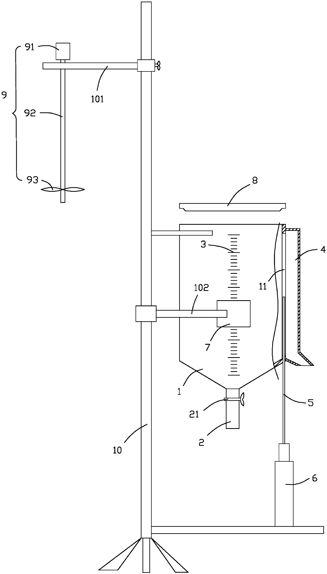
[0023] see figure 1 , in a preferred embodiment of the present invention, an intelligent extraction device includes an extraction main body 1 , a control device and an imaging device 7 . The extraction main body 1 is a hollow structure with an open top, and a liquid outlet pipe 2 connected to the inside of the extraction main body 1 is installed at the bottom, and a liquid valve 21 is installed on the liquid outlet pipe 2; the side wall of the extraction main body 1 A scale line 3 is arranged on the top, and the scale line 3 is vertically arranged along the height direction of the extraction body 1, and the side wall of the part where the scale line 3 is located is made of a transparent material; the side wall of the extraction body 1 is provided with a A port 11, the port 11 and the scale line 3 are arranged at intervals, and the port 11 is also arranged along the height direction of the extraction body 1; the outer wall of the extraction body 1 has a liquid cavity 4, and the...


PUM


Abstract

The invention provides intelligent extraction equipment and belongs to the technical field of extraction equipment. The intelligent extraction equipment comprises an extraction body, a control deviceand camera equipment and is characterized in that a liquid discharge pipe is mounted at the bottom of the extraction body, and a liquid valve is mounted on the liquid discharge pipe; the lateral wallof the extraction body is provided with scale marks, the lateral wall of the extraction body is provided with a port, and the port and the scale marks are arranged at interval; the outer lateral wallof the extraction body is provided with a liquid cavity, and the liquid cavity is communicated with the extraction body through the port; a liquid outlet is formed in the bottom of the liquid cavity;a covering plate covers the port, the covering plate is slidably mounted on the extraction body, and the bottom of the covering plate extends to a position below the bottom of the extraction body andis connected with a slide drive device located outside the extraction body; the control device is connected with the slide drive device and the camera equipment; the camera equipment faces directly tothe part, where the scale marks are located, of the extraction body and is used for shooting the conditions of layered liquid in the extraction body after liquid separation in the extraction body isfinished. By the intelligent extraction equipment, the layered liquid can be obtained automatically without extra auxiliary tools.

Description

technical field [0001] The invention relates to the technical field of extraction equipment, in particular to an intelligent extraction equipment. Background technique [0002] Solution extraction is one of the methods commonly used in chemical, metallurgical, food and other industries to separate two immiscible (or slightly soluble) solvents. This method needs to be carried out with the help of extraction and separation devices. When the existing extraction and separation device obtains the extraction stratified liquid, the liquid pipe and the liquid valve installed at the bottom of the extraction and separation device are mostly used for separation and acquisition. In this way, the upper liquid will drop with the outflow of the lower liquid and be separated from the extraction. The lower liquid attached to the inner wall of the device is confused, and at the same time, if you do not pay attention, the mixed layer will flow out with the lower liquid, thereby affecting the p...

Claims


Application Information

Patent Timeline
Patent Type & Authority Applications(China)
IPC IPC(8): B01D11/04
CPCB01D11/04
Inventor 何本科
Owner 安徽恒达药业有限公司
Learn More