Cut picture acquisition method and device for lens resolution test

A technology of image acquisition and resolution, applied in image analysis, image data processing, instruments, etc., can solve the problems of low accuracy and low efficiency of knife-edge pictures, and achieve the effect of improving test accuracy, avoiding operation errors and improving test efficiency.

Active Publication Date: 2017-06-13
GOERTEK OPTICAL TECH CO LTD
View PDF7 Cites 14 Cited by
  • Summary
  • Abstract
  • Description
  • Claims
  • Application Information

AI Technical Summary

Problems solved by technology

[0003] In view of the above description, based on one purpose of the present invention, the present invention provides a method and device for acquiring a knife-edge picture for lens resolution testing, to solve the problem of low efficiency and low accuracy of manual selection of knife-edge pictures

Method used


Image

  • Cut picture acquisition method and device for lens resolution test
  • Cut picture acquisition method and device for lens resolution test
  • Cut picture acquisition method and device for lens resolution test

Examples


Embodiment 1

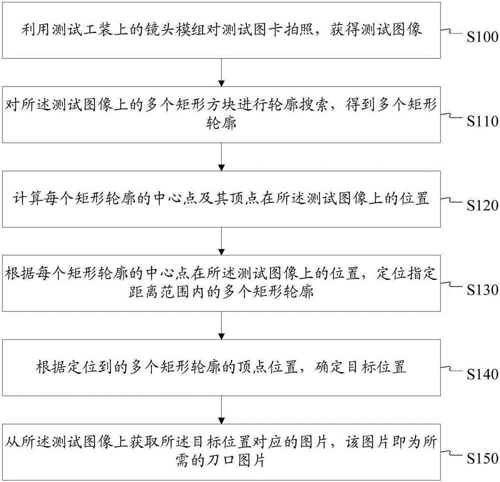
[0029] figure 1 The flow chart of the method for obtaining the knife-edge image for the lens resolution test provided by the embodiment of the present invention, as shown in figure 1 As shown, the methods shown include:

[0030] S100, using the lens module on the test tool to take pictures of the test chart to obtain test images.

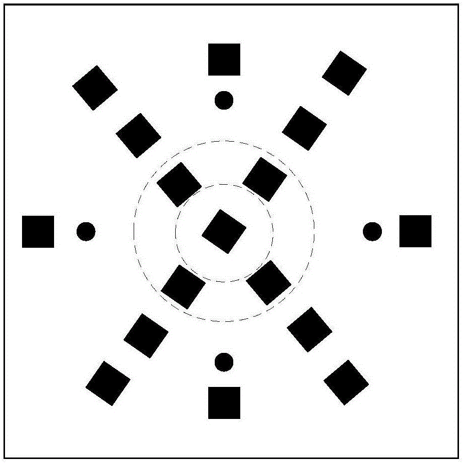
[0031] figure 2 An exemplary test chart card required for a SFR test is shown, such as figure 2 As shown, there are multiple groups of black squares on the test chart, and each group of black squares is set on the test chart obliquely around the center point of the test chart, and multiple groups of black squares are from the center point of the test chart to the edge of the test chart radiation.

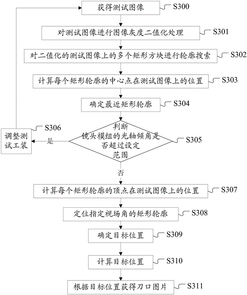
[0032] In the design process, after the test image is obtained, the test image can also be binarized to facilitate the subsequent contour search. Wherein, the test image may be binarized using the existing technology, which is not limited in this e...

Embodiment 2

[0081] Based on the same concept as that of the first embodiment, this embodiment provides a device for acquiring a knife-edge image for lens resolving power testing.

[0082] Figure 6 The structural block diagram of the acquisition device for the knife-edge picture used for the lens resolution test provided by the embodiment of the present invention, such as Figure 6 As shown, the device includes: a test image acquisition unit 61, a contour search unit 62, a position calculation unit 63, a contour positioning unit 64, a target position determination unit 65 and a knife edge image acquisition unit 66;

[0083] The test image acquisition unit 61 is configured to obtain a test image, which is formed by taking pictures of the test chart card by the lens module on the test tool.

[0084] A contour search unit 62, configured to perform contour search on multiple rectangular blocks on the test image to obtain multiple rectangular contours.

[0085] Figure 6 The device in also ...


PUM


Abstract

The invention discloses a cut picture acquisition method and device for a lens resolution test. The method comprises the steps that a lens module on a test tool is utilized to shoot a test graphic card, and a test image is obtained; contour search is performed on multiple rectangular blocks on the test image to obtain multiple rectangular contours; positions of a center point and vertexes of each rectangular contour on the test image are calculated; the rectangular contours within a specified distance range are positioned according to the position of the center point of each rectangular contour on the test image; a target position is determined according to the positions of the vertexes of the positioned rectangular contours; and a picture corresponding to the target position is acquired from the test image, wherein the picture is the needed cut picture. Through the cut picture acquisition method and device, the cut picture in the test graphic card can be automatically acquired for an SFR test, and test efficiency and test precision of a lens production line are improved.

Description

technical field [0001] The invention relates to the technical field of lens optical testing, in particular to a method and device for acquiring a knife-edge image for lens resolution testing. Background technique [0002] At present, the world-recognized lens resolving power test method is to obtain the modulation transfer function (Modulation Transfer Function, MTF) curve of the lens, and the spatial frequency response (spatial frequency response, SFR) test method is a classic method to calculate the MTF curve, but the SFR test A standard picture style is required, and there are strict regulations on the aspect ratio of the picture and the position of the knife edge. If it is used for production testing, the method of manually selecting the picture of the knife edge is inefficient and the accuracy rate is relatively low. Contents of the invention [0003] In view of the above description, based on an object of the present invention, the present invention provides a method...

Claims


Application Information

Patent Timeline
Patent Type & Authority Applications(China)
IPC IPC(8): G06T7/13G06T7/00G06T7/181
CPCG06T7/0004
Inventor 盖增园王仲楼高强
Owner GOERTEK OPTICAL TECH CO LTD
Why Eureka
Try Eureka