AI technical title is built by Patsnap AI team. It summarizes the technical point description of the patent document.
A handle and tripod technology, applied in the field of new aiming tripod handles, can solve the problem of no aiming tripod research and development, etc.
Pending Publication Date: 2018-02-16
SHANGHAI BAISHUN LOCK IND
View PDF12 Cites 4 Cited by
Summary
Abstract
Description
Claims
Application Information
AI Technical Summary
This helps you quickly interpret patents by identifying the three key elements:
Problems solved by technology
Method used
Benefits of technology
Problems solved by technology
[0002] At present, there are two types of gun aiming tripods used in my country and the world, one is small guns equipped with aiming handles, and the other is equipped with handles and aiming tripods. With the progress of society, many countries have implemented secondary This is the second development, using the space inside the handle to install the battery, and the aiming tripod is equipped with a flashlight, but the technology of the aiming tripod has not been fully researched and developed.
Method used
Image
Click on the blue label to locate the original text in one second.
Reading with bidirectional positioning of images and text.
Examples
Embodiment 1
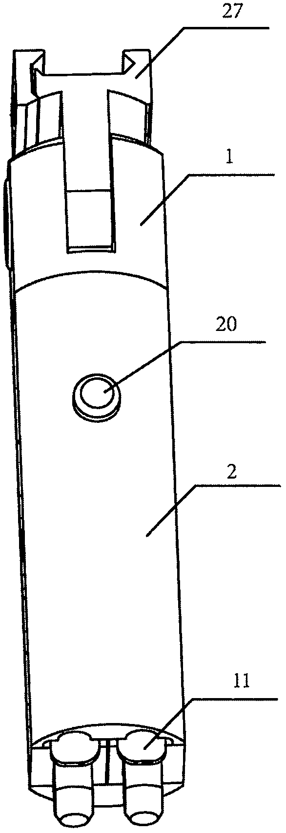
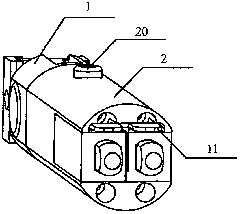
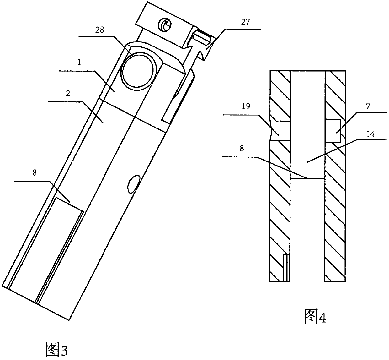
[0031] like figure 1 , figure 2 , image 3 , Figure 4 , Figure 5 , Image 6 , Figure 7 As shown, a novel aiming tripod handle of the present invention includes: a connecting piece 27 with a fixed slot, a fixed pin 28, a handle cover 1, a handle 2, a slider 4, a symmetrically arranged swivel frame 6, and a symmetrically arranged extension arm 23. The locking rod 3, the handle 2 and the handle cover 1 are fixed together, and it is characterized in that there is a slider hole 14 matching the slider 4 inside the handle 2, the slider 4 is placed in the slider hole 14, and the slider 4 There are upper and lower lock openings 18a, 18b on one end of the handle, a guide groove 26 matching the locking rod 3 is opened between the locking opening 18a and the locking opening 18b, the locking rod hole 19 is opened on the handle 2, and the locking rod 3 is set In the locking rod hole 19, the front end of the locking rod 3 is provided with a locking block 17, the locking block 17 ma...
Embodiment 2
[0037]A new type of aiming tripod handle described in Embodiment 1, such as Figure 4 , Figure 7 , Figure 9 As shown, only one locking opening 18b can also be provided, and the upper end of 18b is provided with a guide groove 26 matching the locking bar 3. When opening, press the button 20 on the handle 2, and the locking bar 3 is connected with an integrated locking block. 17. Leaving the lock 18a on the slider 4, the slider 4 is pushed outward under the action of the spring 13, and the symmetrically arranged turret 6 connected to the slider 4 is pushed out and unfolded under the action of the spring 16, The block 10 on one end of the symmetrically arranged turret 6 leaves the symmetrically arranged block 8 on the handle 2, and at the same time, the block 8 enters the notch 15 on the turret 6 to achieve a stable fixing effect.
Embodiment 3
[0039] like Figure 10 , Figure 11 , Figure 12 , Figure 13 The above-mentioned new type of aiming tripod handle shown above can also be manually opened, including a connecting piece 27 for fixing the card slot, a fixing pin 28, a handle cover 1, a handle 2, a slider 4, and a symmetrically arranged turret 6. The extending arm 23 is arranged symmetrically. The handle 2 and the handle cover 1 are fixed together. There is a hole 14 matching the slider 4 inside the handle 2. The slider 4 is placed in the hole 14 of the handle. The two ends of the slider 4 Have positioning rod hole 29, the both sides of handle 2 have symmetrical positioning opening 31a, 31b, positioning rod 3a, 3b is placed in the positioning rod hole 29, spring ( Not noted in this figure), dead bolts 32a, 32b are arranged in the middle of the positioning rods 3a and 3b, and the dead bolts 32a, 32b match the positioning openings 31a, 31b on the handle 2, and guide grooves are provided between the positioning o...
PUM
Abstract
The invention discloses a novel aiming foot stool handle. The novel aiming foot stool handle mainly comprises a connecting part with a fixed clamping groove, a fixing pin, a handle cover, a handle body, a sliding block, symmetric rotating frames, symmetric extension arms and a locking bar; a sliding block hole matched with the sliding block is formed in the handle body, the sliding block is placedin the sliding block hole, locking openings and a guide groove matched with the locking bar are formed in one end of the sliding block, the locking bar is placed in a locking bar hole in the handle,the front end of the locking bar is provided with a locking block which is matched with a locking opening in the sliding block, the other end of the locking bar is provided with a button, the slidingblock is movably connected with the symmetric rotating frames, and check blocks are arranged on the two sides of the handle. When the handle is started, the button on the handle is pressed down, the locking bar is connected with an integrated locking block which is away from the lock opening in the sliding block, the sliding block is pushed outwards un the effect of a spring, meanwhile, the rotating frames connected with the sliding block are pushed outwards, and are unfolded under the effect of the spring, and check blocks on the rotating frames enter concave openings in the rotating frames to form a bearing fixing structure.
Description
[0001] The invention relates to a novel aiming tripod handle, in particular to a firearm handle that can be converted into an aiming stand. Background technique [0002] At present, there are two types of gun aiming tripods used in my country and the world, one is a small gun with an aiming handle, and the other is equipped with a handle and an aiming tripod. With the progress of society, many countries have implemented secondary In the first development, the battery is installed in the space in the handle, and the flashlight is installed on the aiming tripod, but the technology of aiming the tripod has not been fully researched and developed. Contents of the invention [0003] The invention relates to a new type of aiming tripod handle, more specifically relates to a handle that can be converted into an aiming tripod, mainly including a connecting piece 27 with a fixing slot, a fixing pin 28, a handle cover 1, a handle 2, a slider 4, symmetrically arranged The swivel frame 6...
Claims
Application Information
Patent Timeline
Application Date:The date an application was filed.
Publication Date:The date a patent or application was officially published.
First Publication Date:The earliest publication date of a patent with the same application number.
Issue Date:Publication date of the patent grant document.
PCT Entry Date:The Entry date of PCT National Phase.
Estimated Expiry Date:The statutory expiry date of a patent right according to the Patent Law, and it is the longest term of protection that the patent right can achieve without the termination of the patent right due to other reasons(Term extension factor has been taken into account ).
Invalid Date:Actual expiry date is based on effective date or publication date of legal transaction data of invalid patent.

