Power tool

a technology of power tools and motors, applied in the field of power tools, can solve the problems of poor accuracy of motor speed control by users, above still presents problems, etc., and achieve the effect of accurate matching of body output speed

Inactive Publication Date: 2006-04-04
BLACK & DECKER INC
View PDF17 Cites 466 Cited by
  • Summary
  • Abstract
  • Description
  • Claims
  • Application Information

AI Technical Summary

Benefits of technology

[0010]It is thus an object of the present invention to alleviate the above shortcomings by providing a power tool including, a body which houses a motor, a first output shaft operatively coupled to the motor, and an attachment for engagement with the body, wherein the attachment includes an input shaft for operative engagement with the first output shaft of the body when the attachment is engaged with the body. The attachment includes a further output shaft for transmitting rotational motion derived from rotational motion of the attachment input shaft. The power tool characterised by both the body and the attachment having a respective gear mechanism for causing a gear change in rotational speed as between the input and the output of the respective gear mechanism, the combination of the body and the attachment thereby providing a power tool with a plurality of serially-coupled gear mechanisms. This combination provides an advantage over known power tools in that more accurate matching of the body output speed to the attachment input speed can be achieved than has hitherto been the case.

Problems solved by technology

Alternatively, the accuracy of control of the motor speed by a user may not be very good due to vibration of the tool during use.
The above still presents problems, however.
However, if the motor output can itself be geared, then each attachment may only need a relatively small, simple gear mechanism of its own in order to become well tuned to its specific task.

Method used


Image

  • Power tool
  • Power tool
  • Power tool

Examples


Embodiment Construction

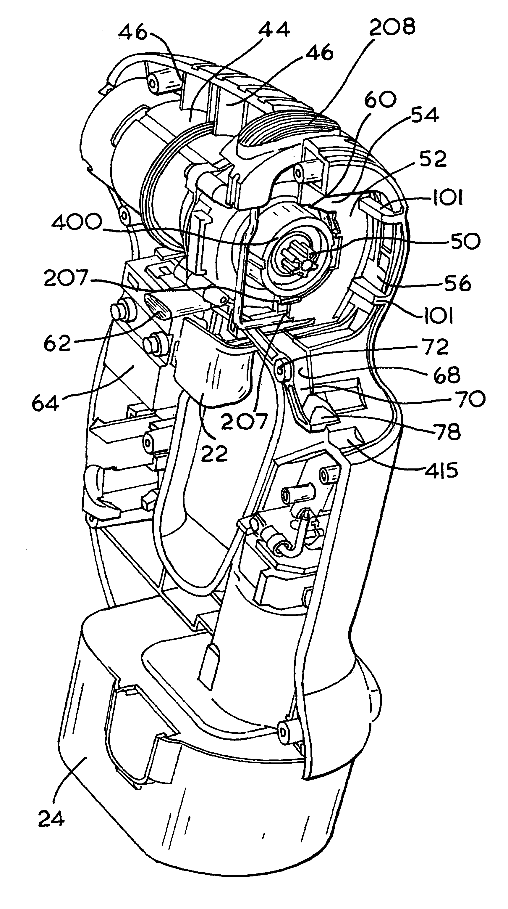
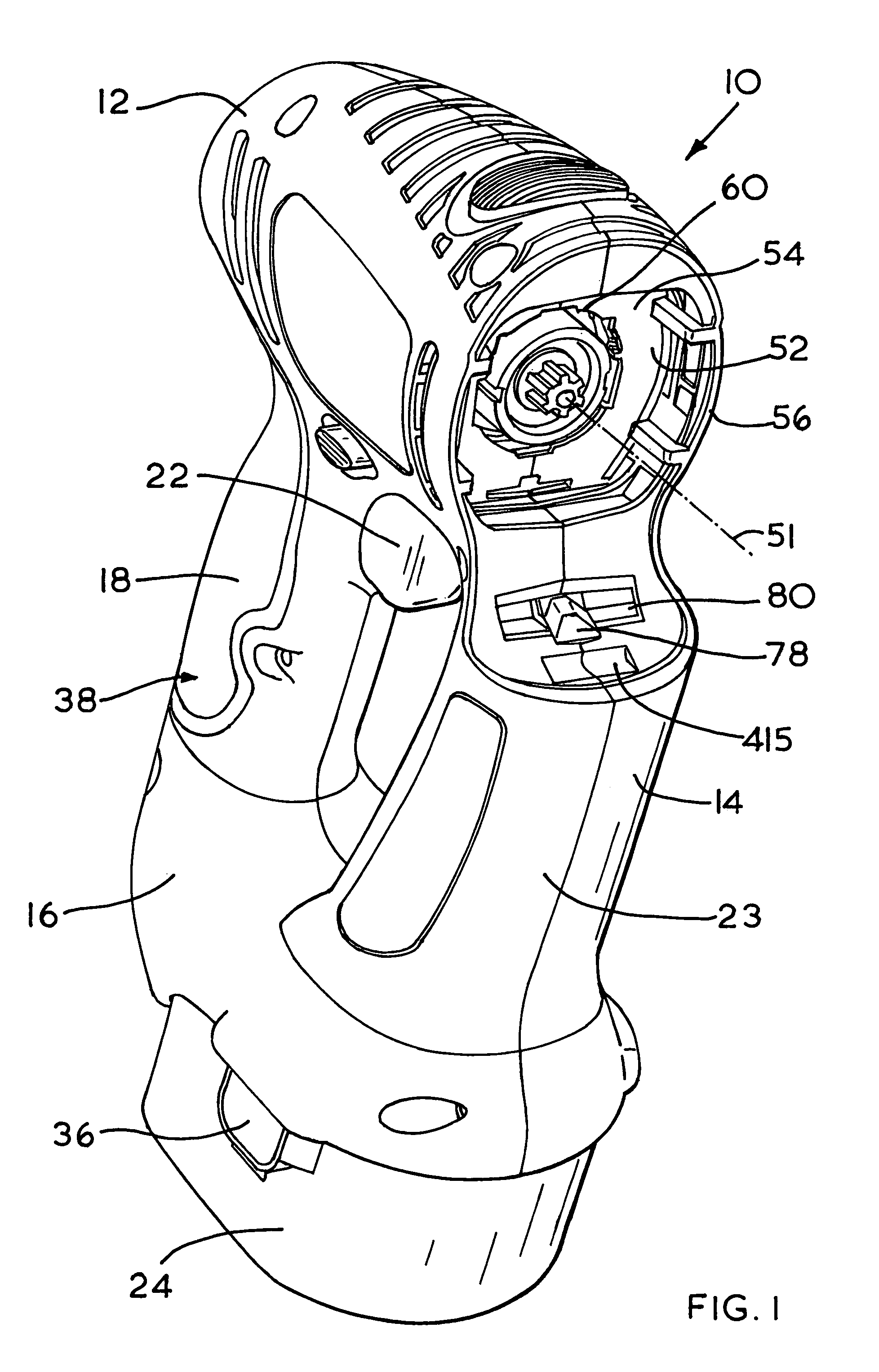
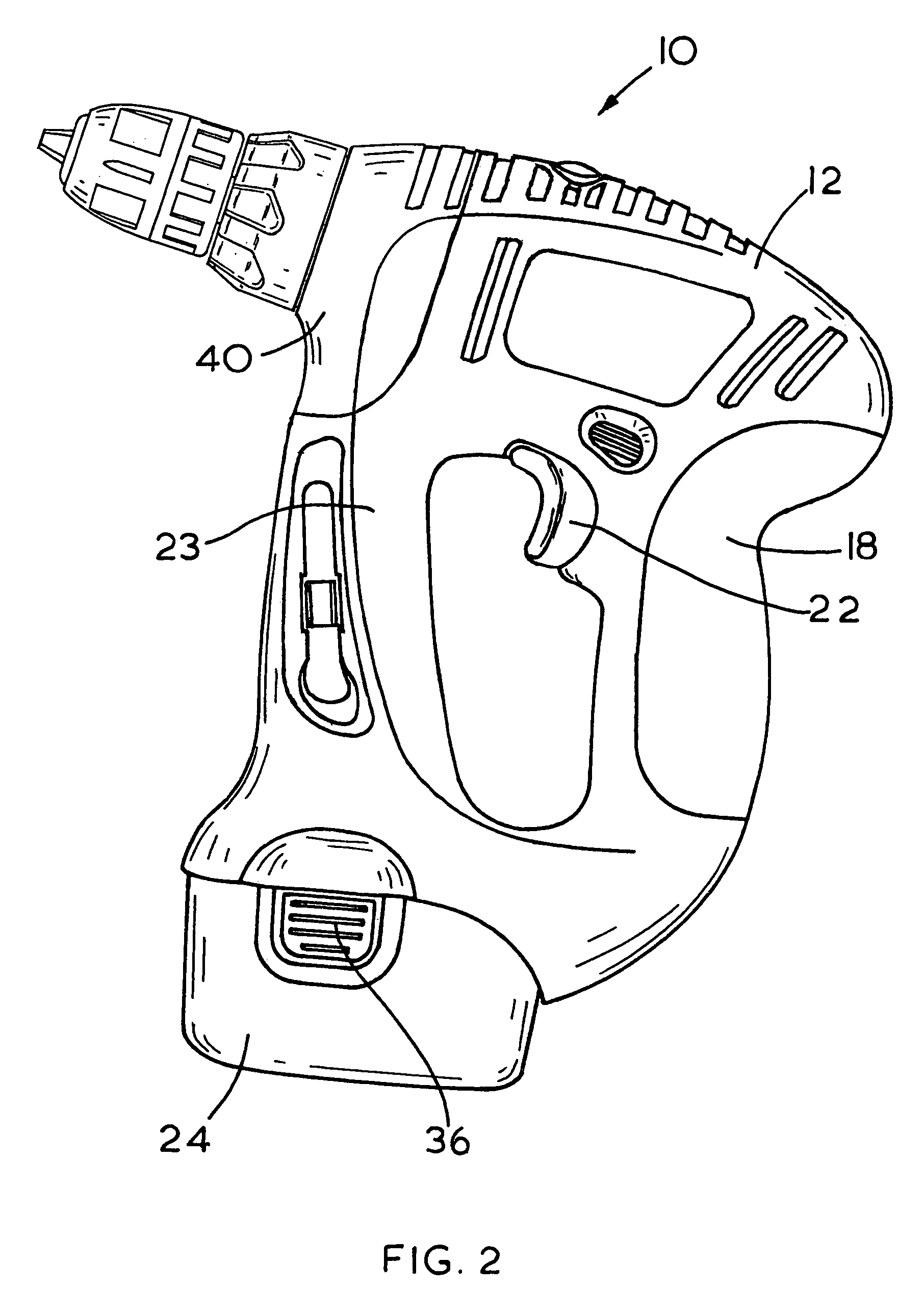
[0040]Referring now to FIG. 1, a power tool shown generally as (10) comprises a main body portion (12) conventionally formed from two halves of a plastics clam shell (14, 16). The two halves of the clam shell (14, 16) are fitted together to encapsulate the internal mechanism of the power tool (10), to be described later.

[0041]The body portion (12) defines a substantially D-shaped body, of which a rear portion (18) defines a conventional pistol grip handle to be grasped by the user. Projecting inwardly of this rear portion (18) is an actuating trigger (22) which is operable by the user's index finger in a manner conventional to the design of power tools. Since such a pistol grip design is conventional, it will not be described further in reference to this embodiment.

[0042]The front portion (23) of the D-shaped body serves a dual purpose in providing a guard for the user's hand when gripping the pistol grip portion (18) but also serves to accommodate battery terminals (25) (FIG. 5a) a...


PUM


Abstract

A power tool includes a body housing a motor with a first output shaft and an attachment for engagement with the output shaft. The attachment includes an output shaft which transmits rotational motion derived from the rotational motion of the motor and further includes a gear mechanism enabling a gear change in rotational speed between its input and output. A combination of the body and the attachment thereby provides a plurality of serially-coupled gear mechanisms.

Description

[0001]This application is a continuation-in-part of U.S. patent application Ser. No. 09 / 139,200 filed Aug. 25, 1998 entitled “Power Tool Having Interchangeable Tool Head”, which issued as U.S. Pat. No. 6,286,611 on Sep. 11, 2001.FIELD OF THE INVENTION[0002]The present invention relates to power tools and more particularly, to a power tool which may be adapted to perform several different tasks.BACKGROUND OF THE INVENTION[0003]Power tools are known which comprise a body which houses a motor and an attachment for coupling with the body in order to form a certain task such as drilling or sawing of a workpiece. The attachment is usually task-specific and so will generally need to be adapted for the task.[0004]An example of such a power tool is shown in EP-A-899,063, whereby a composite power tool is formed from a body and any one of a plurality of attachments. The body houses an electric motor for supplying a driving force to the attachment mounted on the body, whereby the body of the t...

Claims


Application Information

Patent Timeline
Patent Type & Authority Patents(United States)
IPC IPC(8): E21B17/22B25F3/00
CPCB25F3/00
Inventor DRIESSEN, LEO
Owner BLACK & DECKER INC
Why Eureka
Try Eureka