Map matching method and apparatus for navigation system

a mapping system and mapping technology, applied in traffic control systems, navigation instruments, instruments, etc., can solve the problems of inability to obtain absolute position values, inability to detect the change of direction, and impaired accuracy of detecting the current position of the vehicle, so as to accurately match the current vehicle position and avoid erroneous display

Active Publication Date: 2009-10-13
ALPINE ELECTRONICS INC
View PDF5 Cites 75 Cited by
  • Summary
  • Abstract
  • Description
  • Claims
  • Application Information

AI Technical Summary

Benefits of technology

[0012]It is, therefore, an object of the present invention to provide a map matching method and apparatus for a navigation system which is capable of more accurately estimating a current position of a vehicle when a GPS signal is lost or otherwise invalid.
[0018]According to the present invention, the map matching method and apparatus is able to accurately match the current vehicle position on the correct road segment. Thus, the map matching method of the present invention can avoid erroneous display of the current vehicle position on the wrong road even when the GPS signals are invalid for a relatively long period of time.

Problems solved by technology

Although the sensors (gyroscope and speed sensor) of the vehicle are able to obtain relative position values with respect to the previous position, it is not possible to obtain absolute position values.
When the axis does not accurately correspond to the axis about which the vehicle actually rotates, error will be involved in detecting the change of direction.
Because of the above reasons, errors may arise in determining an amount of change in the vehicle travel direction, and the accuracy of detecting the current position of the vehicle will thereby be impaired.
The errors will be accumulated by time, i.e., the longer the time, the larger the errors.
Because of noises contained in the GPS signals, the position data obtained from the GPS signals also contain errors, for example, about 100 meter radius.
However, appropriate GPS signals may not always be available, for example, in a downtown area with many tall buildings where GPS signals are reflected and interfered by the buildings.
In another example, when a vehicle is in a valley between tall mountain walls, the minimum number of visible GPS satellites may not be available.
In such a situation where the GPS signals are lost or insufficient, the position errors will be accumulated because the navigation system has to rely solely on the dead reckoning process.
Since the GPS navigation requires the minimum number of visible GPS satellites, sufficient GPS signals may not be available depending on particular locations in such a downtown area.
Generally, since GPS satellites stay in the same locations in the sky, such problems as GPS signal loss will happen at the same locations in the city.

Method used


Image

  • Map matching method and apparatus for navigation system
  • Map matching method and apparatus for navigation system
  • Map matching method and apparatus for navigation system

Examples


Embodiment Construction

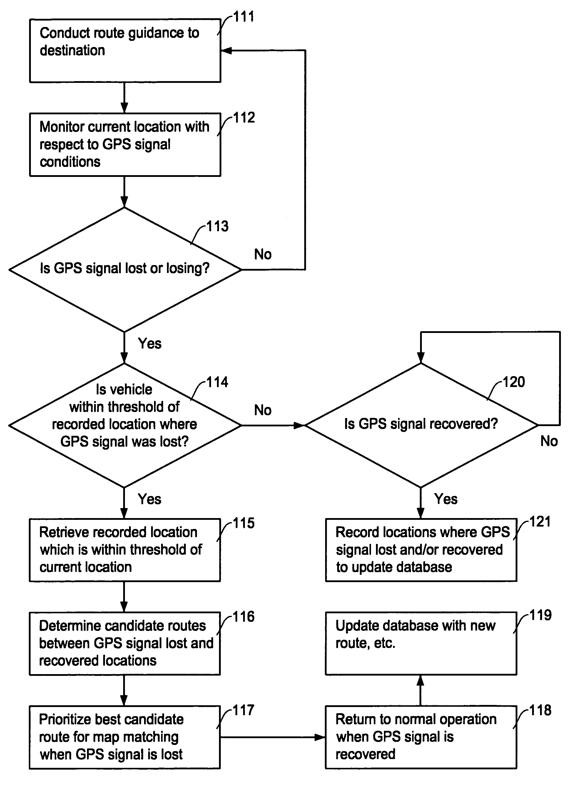
[0028]The map matching method in the present invention is explained with reference to the accompanying drawings. The present invention provides a map matching method and apparatus that enables to accurately estimate a current position of the vehicle when sufficient GPS signals are not available. The present invention predicts the path (road segment) that the user is most likely to take and prioritize the predicted path when performing a map matching processing to determine the current location on the map.

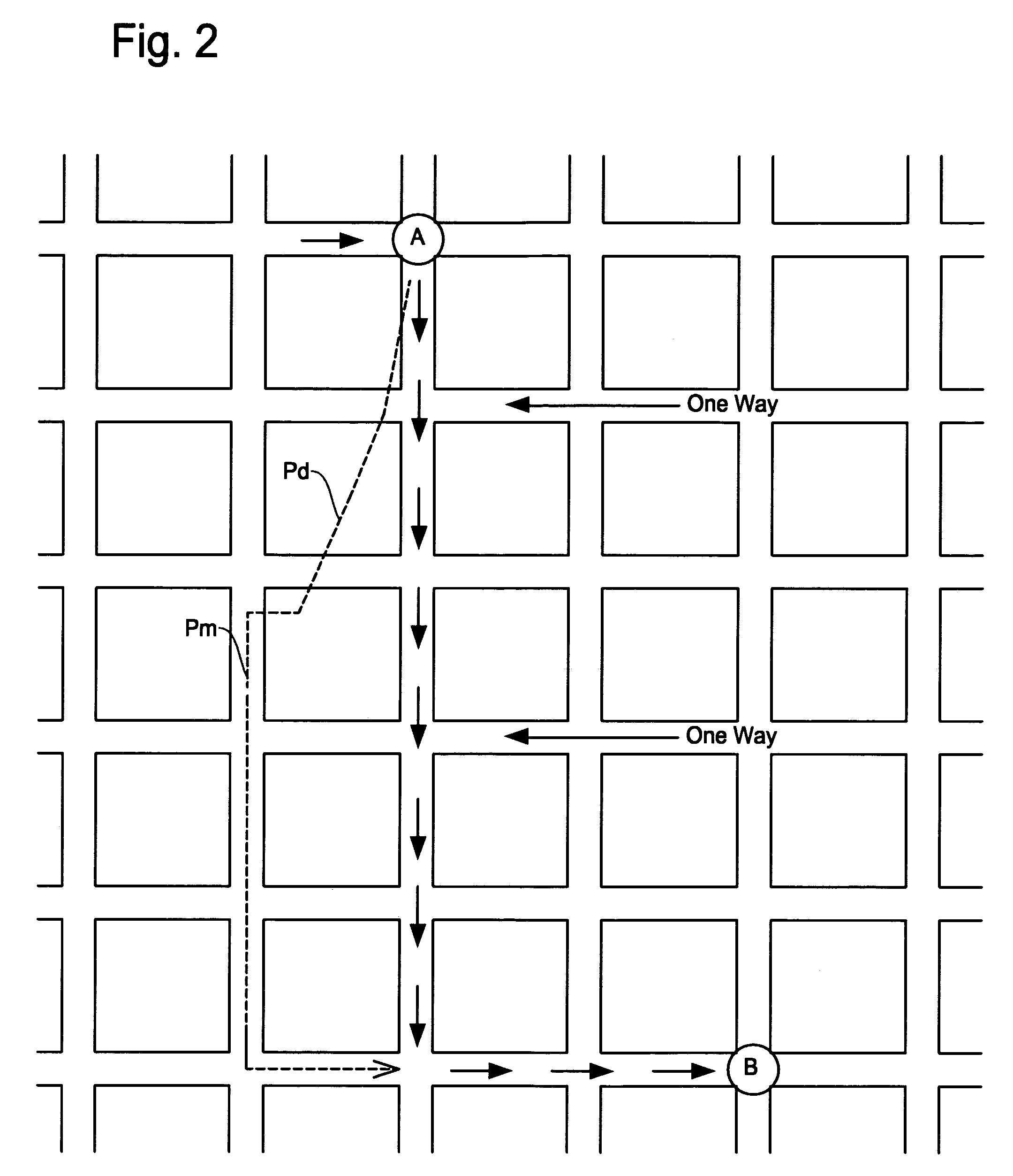
[0029]FIGS. 3A and 3B are schematic diagrams showing a basic principle of operation in the map matching method and apparatus of the present invention for the same condition as that of FIG. 2. During the period when the GPS signal is lost, the present invention so operates that the errors accumulated by the dead reckoning will not adversely affect the map matching. This can be achieved in such a way that the map matching method constantly checks the route that is most likely being us...


PUM


Abstract

A map matching method and apparatus for a navigation system estimates a location of the navigation system on a correct road segment when a GPS signal is invalid. The map matching method creates a database of pairs of locations at which the navigation system encountered GPS signal loss and recovery in the first time. The navigation system conducts a map matching processing when the GPS signal is lost in the second time at the recorded location by incorporating various additional factors to match the current position with a correct road segment. The various additional factors, in addition to the measured data by a dead reckoning process, include road class, road accessibility, road angle, proximity to candidate road, etc.

Description

FIELD OF THE INVENTION[0001]This invention relates generally to a map matching method for a navigation system, and more particularly, to a map matching method and apparatus for creating a database of pairs of locations at which the navigation system encountered GPS signal loss and recovery in the first time, and for conducting a map matching processing when the GPS signal is lost in the second time at the recorded location by incorporating various additional factors to match the current vehicle position with a correct road segment.BACKGROUND OF THE INVENTION[0002]Navigation system are widely used today. On a monitor screen of a navigation system, typically, the current position of the vehicle and a route on which the vehicle is running are superimposed on a map image of a region in which the vehicle is currently travelling. For such a navigation system, it is essential to determine the current position as accurately as possible under various different driving conditions.[0003]With s...

Claims


Application Information

Patent Timeline
Patent Type & Authority Patents(United States)
IPC IPC(8): G01C21/00G01S19/48
CPCG01C21/30
Inventor TASHIRO, ERIC
Owner ALPINE ELECTRONICS INC
Why Eureka
Try Eureka