System and Method for Driving LED

a driving led and system technology, applied in the field of power conversion, can solve the problems of preventing the voltage type regulator from acting, presenting a very difficult load for the voltage type regulator, and the characteristic of the diode type volt amp, so as to reduce the monetary cost, accurate estimate the output current, and maintain global stability

Active Publication Date: 2007-12-13
CHEMTRON RES
View PDF1 Cites 149 Cited by
  • Summary
  • Abstract
  • Description
  • Claims
  • Application Information

AI Technical Summary

Benefits of technology

[0010] In still another embodiment of the invention, a sliding mode with pulse current averaging control for driving one or plurality of LEDs driver is proposed. The idea of pulsed current averaging is that in many switch-mode power supply topologies, it is possible to measure input or inductor current in order to obtain an accurate estimate of output current. Sometimes this is called an “estimator” or “observer” by control theorists. Thus, in applications such as those that require output current regulation, this becomes a powerful tool to help controller design. Remarkably, digital implementation of the approach should not require additional analog-digital (A / D) or D / A converters because of some of its special features. Thus, it is possible to get advanced digital performance at substantially reduced monetary cost. Traditionally, in peak current mode control regulation, a user specifies a reference current, and then the power switch switches off when the inductor current rises to this reference current (minus an appropriate slope compensation to maintain global stability). However, in pulsed current averaging, we propose to regulate differently: we propose to regulate directly the length of the power switch on time (Ton) in order to create the desired peak value Ip. We then relate this peak value to the load output current's average value. Hence, load current regulation becomes possible. Since LEDs require current regulation instead of voltage regulation, this makes pulsed current a prime candidate for its application. To demonstrate the proposed regulation approach and show its potential, we describe the pulsed current averaging regulation, using a simple hysteretic controller. The sliding mode control will include the steps of turning on the power switch at the edge of the lock oscillator; starting counting on time Ton; measuring LEDs average current; comparing said measured current to a set LEDs current and generating the sign of Ton change plus if LEDs current is smaller than the set current and minus if LEDs current is larger than the set current; stop counting on time at set on time Ton=Ton+ / −Δton and turning off the power switch; adjusting new on time for the next cycle either increasing or decreasing previous cycle Ton time based on the sign of Ton change.

Problems solved by technology

An LED, having a diode type volt amp characteristic, presents a very difficult load for a voltage type regulators.
In practically all switching LED drivers current through LED is a stream of high frequency pulses, and the described above feedback introduces phase delays, makes poor dynamic response, prevents regulator from acting within one switching cycle.

Method used


Image

  • System and Method for Driving LED
  • System and Method for Driving LED
  • System and Method for Driving LED

Examples


Embodiment Construction

[0037] The embodiments of the present invention will be described below with reference to the accompanying drawings. Like reference numerals are used for like elements in the accompanying drawings.

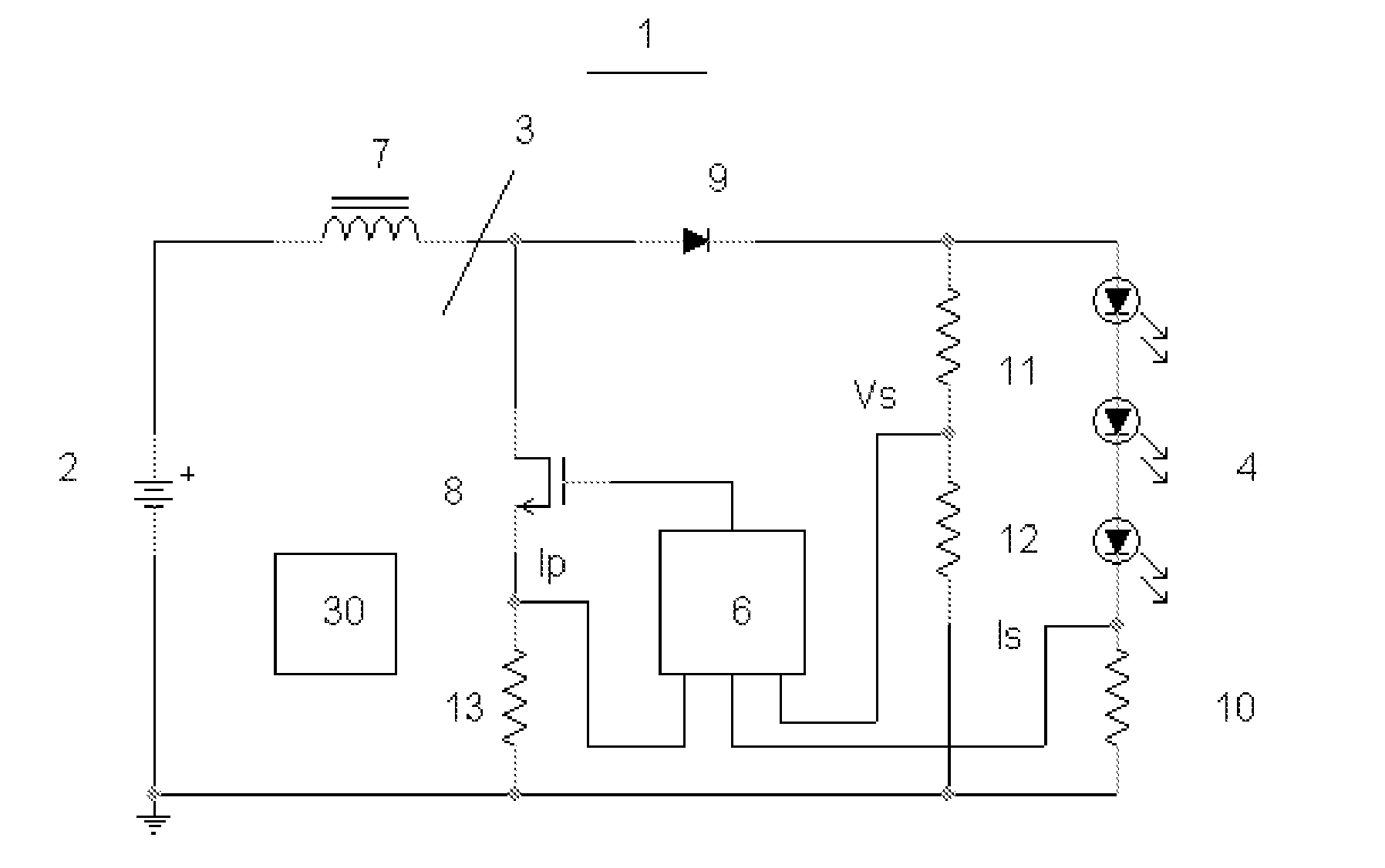
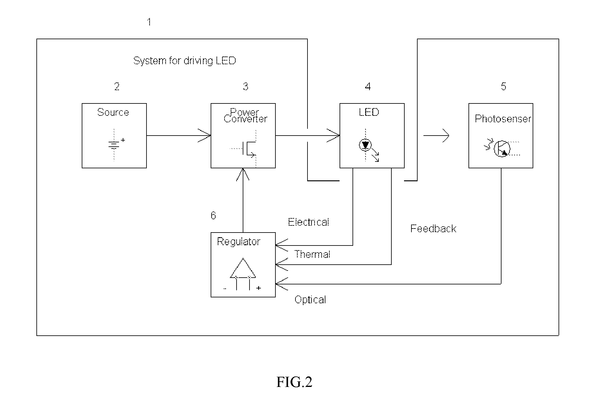
[0038]FIG. 2 is a system for driving one or plurality of LEDs, according to one embodiment of the invention. The system 1 includes an energy source 2 and a switching power converter 3 driving a string of LEDs 4. The performance of LEDs is measured by electrical and thermal sensors (not shown separately from LED unit 4) and a photosensor 5. These sensors generate electrical, thermal and optical feedback channels coupled with a regulator 6 controlling the output of the power converter 3. The regulator 6, according to one embodiment of the invention, needs to have as minimum a single electrical feedback. Yet, it may use additional thermal and optical feedback channels for enhanced performance, according to another embodiment of the invention. The energy source 2 is an AC / DC converter, connec...


PUM


Abstract

A system drives one or plurality of LEDs regulating their brightness by controlling LEDs average current or voltage. The system includes a switching power converter and an integrated digital regulator with at least one of electrical, thermal and optical feedbacks. The regulator is constructed as a hysteretic peak current mode controller for continuous mode of operation of the power converter. For discontinuous mode of operation of the power converter a pulse averaging sliding mode control is being used. Average LED current is measured by integrating LED pulse current at off time and hysteretically adjusting on time of the power switch. Input battery is protected from discharging at abnormally low impedance of the output.

Description

RELATED APPLICATIONS [0001] This application is a divisional of and claims priority to Anatoly Shteynberg et al., U.S. patent application Ser. No. 11 / 142,859, filed May 31, 2005, entitled “System and Method for Driving LED”, which is commonly assigned herewith, the contents of which are incorporated herein by reference, and with priority claimed for all commonly disclosed subject matter, and further claims priority to Anatoly Shteynberg et al, U.S. Provisional Application Ser. No. 60 / 611,539 filed on Sep. 21, 2004, entitled System And Method For Driving LED.FIELD OF THE INVENTION [0002] The present invention relates generally to power conversion, and more specifically, to a system and method for driving LEDs, and particularly to integrated LED drivers with digital controllers. BACKGROUND OF THE INVENTION [0003] It is known in the Industry a few LEDs drivers, like charge pump with the multi output current mirror from National Semiconductor. These drivers cannot economically boost inp...

Claims


Application Information

Patent Timeline
Patent Type & Authority Applications(United States)
IPC IPC(8): H05B41/36H02M1/00H05B44/00
CPCH02M3/157H02M2001/0009H05B33/0815H05B33/086H05B33/0818H05B33/0872Y02B20/341G05F1/618H05B37/02H05B33/0869H05B45/20H05B45/22Y02B20/30Y02B20/40H05B45/3725H05B45/12H05B45/38H05B45/10H05B45/56H05B47/105H05B47/165H02M1/0009H05B47/11
Inventor SHTEYNBERG, ANATOLYRODRIGUEZ, HARRY
Owner CHEMTRON RES
Why Eureka
Try Eureka