Method and apparatus for controlling a temperature-controlled probe

a temperature-controlled probe and temperature-controlled technology, applied in the field of probes, can solve the problems of osteoarthritis, long healing process, nerve injury, etc., and achieve the effect of reducing overshoot and fine control

Inactive Publication Date: 2005-09-06
ORATEC INTERVENTIONS
View PDF131 Cites 477 Cited by
  • Summary
  • Abstract
  • Description
  • Claims
  • Application Information

AI Technical Summary

Benefits of technology

[0021]Thus, the present invention enables probe temperature to rapidly be ramped in magnitude to a set-point value close to the desired target probe temperature, and thereafter to be controlled with the PID algorithm with much finer granularity of control. As a result, overshoot is minimized.

Problems solved by technology

When soft tissue in a joint is damaged, the healing process is often long and painful.
Using current treatments, many people with injured joints suffer from prolonged pain, loss of motion, nerve injury, and some develop osteoarthritis.
The soft tissue in many injured joints never heals enough to return the damaged joint to its full range of function.
In particular, applying controlled thermal energy to soft tissue in an injured joint can cause the collagenous tissue to shrink, thereby tightening unstable joints.
While these probes meet the basic need for rehabilitative thermal treatment of soft tissues, such as collagen tissues, many suffer from temperature overshoot and undershoot fluctuation, causing unpredictable results in the thermal alteration.
Other approaches seem to be less successful in their attempts to delivery uniform energy from a probe in a thermally unstable environment.
But not unlike other prior art probes, probe temperature can become unstable as heat from the probe is dissipated into the mass of the treated tissue.
This can be especially troublesome when treating dense tissue, which acts as a heat sink and thereby requires additional energy input to maintain a desired target temperature.
In general, a system is over-damped when its damping factor is greater than one, and the system will have a slow response time.
A system is critically damped when its damping factor is exactly one.
In an under-damped system, “ringing” is a problem and can result in the momentary application of temperatures that are too high for the safe heating of soft tissue.
When this occurs, damage to the soft tissue may result from charring, ablation or the introduction of unwanted and harmful effects on the soft tissue causing injury.
For example, during hyperthermia, which is defined as the treatment of diseased soft tissue by raising the bodily temperature by physical means, some prior art probes have difficulty in providing smooth and consistent heating because the preferred materials for the energy delivery electrodes are highly thermally responsive materials.
Such materials generally do not retain large amounts of heat energy.
At initiation, the controller rapidly heats the probe to achieve the target temperature, which can result in an overshoot problem.
During application, probe contact with large tissue masses tends to cause underdamped fluctuations in the probe temperature due to vast differences in the temperature of the surrounding tissue mass.
Likewise, one skilled in the art will appreciate that similar problems may occur during a desired reduction in the soft tissue temperature.
Applications using larger probes typically need relatively large amounts of power to reach and maintain the desired temperature.
However, the typical prior art controller uses the same method to control the power output for different probes and does not change the control process in response to different types of probes, further contributing to overshoot and undershoot problems.

Method used


Image

  • Method and apparatus for controlling a temperature-controlled probe
  • Method and apparatus for controlling a temperature-controlled probe
  • Method and apparatus for controlling a temperature-controlled probe

Examples


Embodiment Construction

[0038]The presently preferred embodiment of the present invention is depicted in FIG. 15. However to arrive at a better understanding of FIG. 15, it is useful to first consider FIGS. 1-14, which are applicable to the invention described in U.S. Pat. No. 6,162,217 and will lead to a better understanding of the present invention. The inventions described in the '217 patent will be referred to herein as the parent invention, or the invention in the '217 patent.

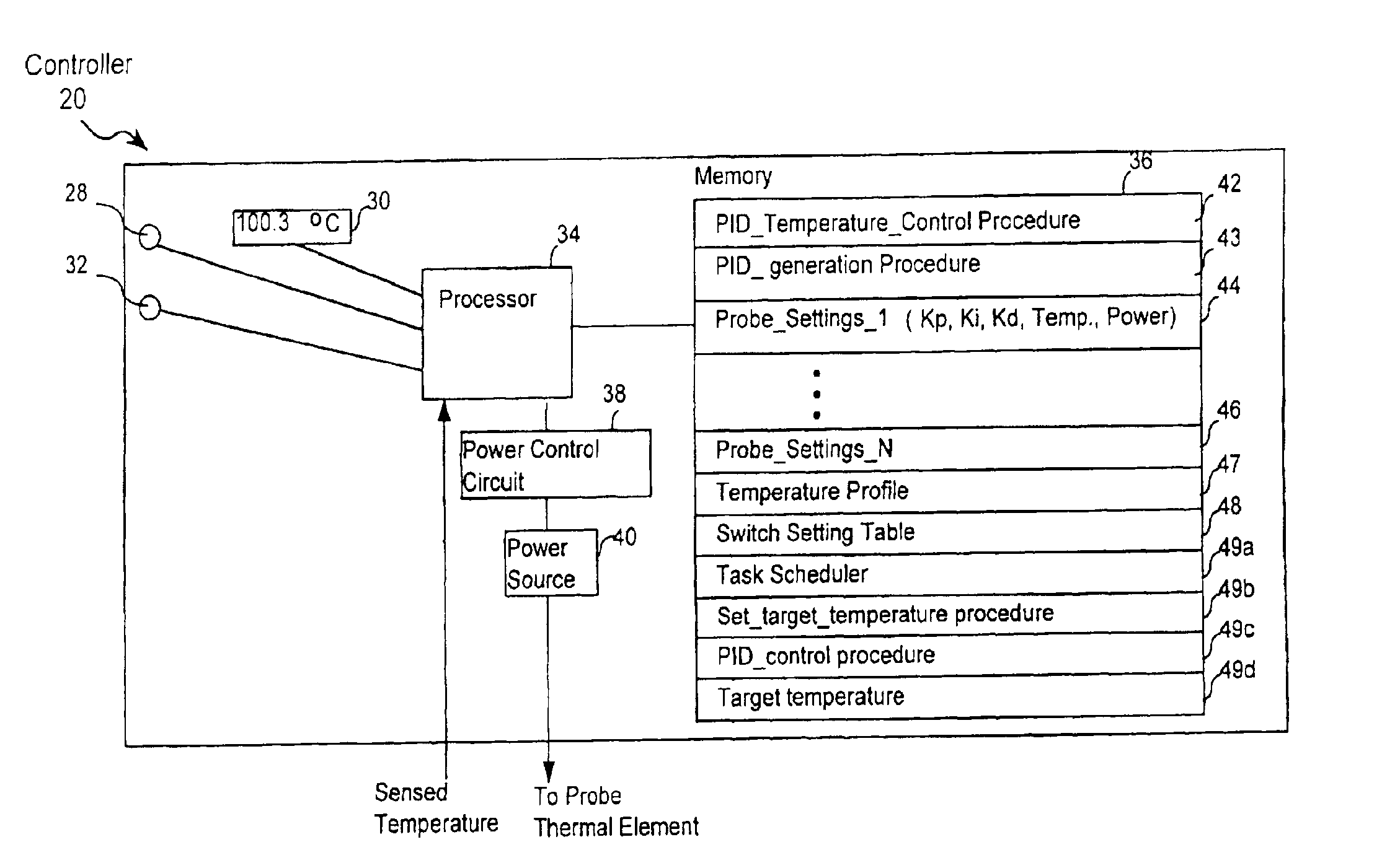
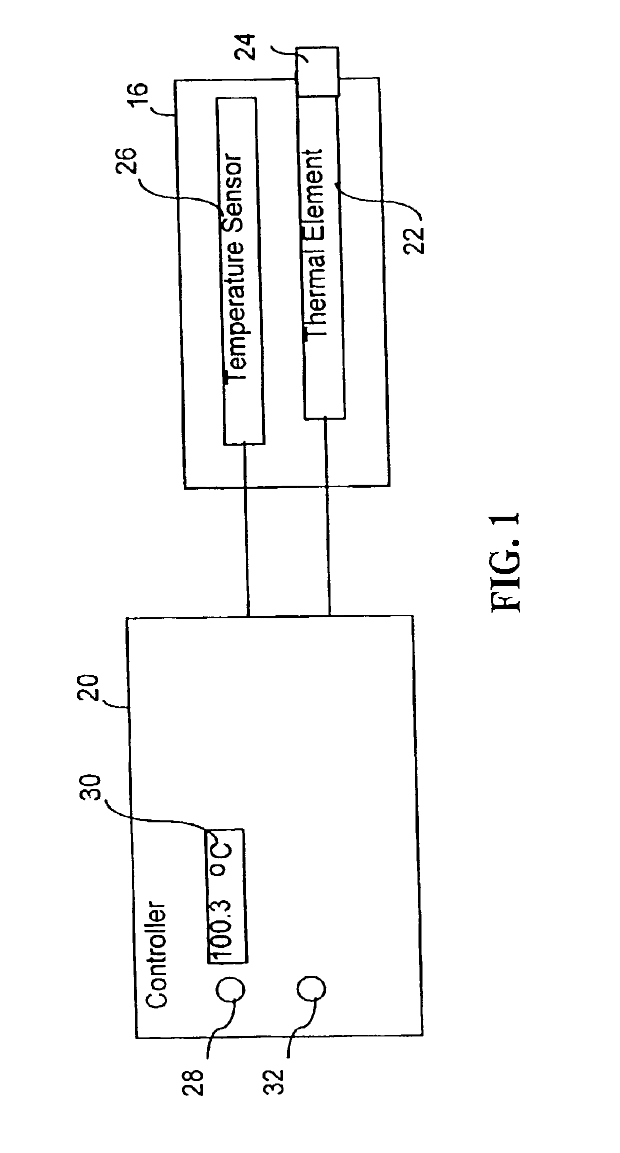
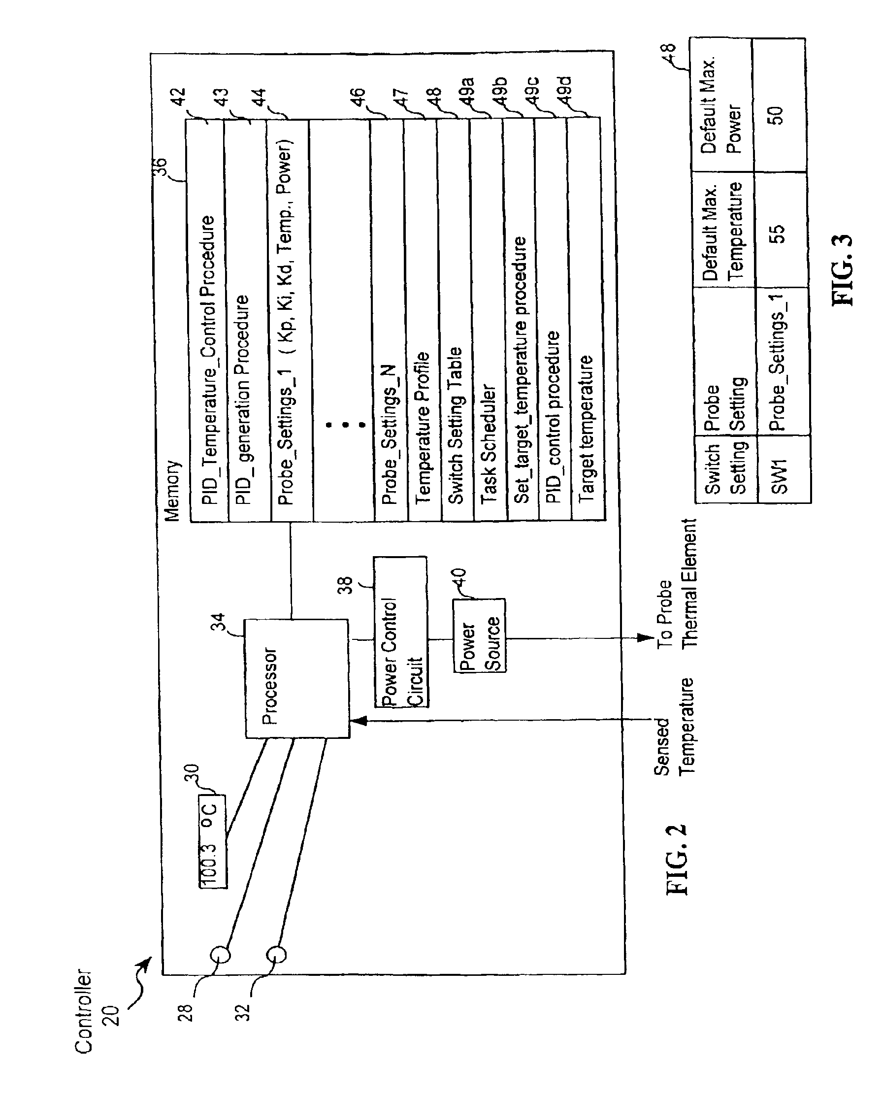
[0039]Turning, then, to FIG. 1, the presently preferred invention as well as the parent invention include a probe 16 and a temperature controller 20 (or a generator 20) that is coupled to the probe. As shown in FIG. 1, a thermal element 22 is attached to a probe tip 24 of probe 16. Thermal element 22 can be used to alter temperature of tissue being treated with probe 16, by heating or cooling. Without limitation, thermal element 22 may include at least one of a transducer that delivers RF energy to the tissue, a resistive heating...


PUM

PropertyMeasurementUnit
timeaaaaaaaaaa
temperatureaaaaaaaaaa
poweraaaaaaaaaa

Abstract

A thermal energy controller system useful in medical procedures includes a controller coupled to a probe, and a thermal element to vary probe temperature. The controller includes memory storing a non-continuous algorithm that permits user-selectable settings for various probe types such that controller operation is self-modifying in response to the selected probe setting. Probe output power Pout is constant in one mode to rapidly enable probe temperature to come within a threshold of a target temperature. The controller can then vary Pout dynamically using a proportional-integral-derivative (PID) algorithm Pout=Kp·P+Ki·I+Kd·D, where feedback loop coefficients Kp, Ki, Kd can vary dynamically depending upon magnitude of an error function e(t) representing the difference between a user-set desired target temperature and sensed probe temperature. Advantageously, target temperature can be rapidly attained without overshoot, allowing the probe system to be especially effective in arthroscopic tissue treatment.

Description

RELATIONSHIP TO PENDING APPLICATION[0001]This is a continuation-in-part of applicant's U.S. patent application Ser. No. 09 / 738,944 filed 14, Dec. 2000 now abandoned and entitled “Method and Apparatus for Controlling a Temperature-Controlled Probe”, which application is a continuation of U.S. patent application Ser. No. 09 / 296,690 filed 21, Apr. 1999, now U.S. Pat. No. 6,162,217 (issued 19, Dec. 1999), entitled “Method and Apparatus for Controlling a Temperature-Controller Probe”.FIELD OF THE INVENTION[0002]The invention relates generally to medical probe devices, and more particularly to probes whose temperature may be controlled in a thermally-discontinuous environment to vary thermal energy delivered to tissue during a medical procedure.BACKGROUND OF THE INVENTION[0003]The most abundant tissue in the human body is soft tissue, and most soft tissue is collagen. Indeed, over 90% of the organic matter in tendons and ligaments is collagen. The connective tissue in joints is comprised ...

Claims


Application Information

Patent Timeline
Patent Type & Authority Patents(United States)
IPC IPC(8): A61B18/12A61B18/08A61B18/04A61B18/02A61B18/14A61B18/00A61B17/00G01K7/00A61B17/56
CPCA61B18/04A61B18/1206A61B18/08A61B18/14A61B2017/00084A61B2017/00482A61B2018/00642A61B2018/00684A61B2018/00702A61B2018/00791A61B2018/00988A61B2018/0237A61B2018/0262
Inventor KANNENBERG, DONALD P.MARION, DUANE W.
Owner ORATEC INTERVENTIONS
Why Eureka
Try Eureka