Laser module

a laser module and laser technology, applied in the direction of lasers, semiconductor laser structural details, semiconductor lasers, etc., can solve the problems of shortening the optical transmission distance and unsatisfactory overshoot of light intensity, and achieve the effect of simple, reliable and inexpensive implementation

Inactive Publication Date: 2006-03-14
SAMSUNG ELECTRONICS CO LTD
View PDF23 Cites 1 Cited by
  • Summary
  • Abstract
  • Description
  • Claims
  • Application Information

AI Technical Summary

Benefits of technology

[0009]The present invention overcomes the above-described problem, and provides additional advantages, by providing a laser module having a low pass filter to minimize the overshoot in the optical module in case the laser diode is used as an optical source.
[0010]According to one aspect of the invention, a laser module having a low pass filter is provided to increase the transmission distance by reducing the frequency chirping in the laser module of a 1.55 um beam wavelength.
[0013]Still another aspect of the invention is that the present invention may be realized in a simple, reliable, and inexpensive implementation.

Problems solved by technology

During operation, an undesirable overshoot of light intensity occurs when the state of laser diode transits from off-state (0-level) to on-state (1-level).
Further, as the frequency chirping increases as the intensity overshoot grows, a laser module of a 1.55 um beam wavelength with large overshoot has the problem of shorting the optical transmission distance.

Method used


Image

  • Laser module
  • Laser module
  • Laser module

Examples


Embodiment Construction

[0021]A preferred embodiment of the present invention will be described herein below with reference to the accompanying drawings. For the purposes of clarity and simplicity, well-known functions or constructions are not described in detail as they would obscure the invention in unnecessary detail.

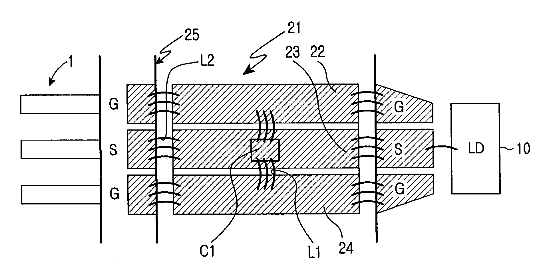
[0022]The principle teachings of the present invention is to implement a low-pass filter to an input end of the laser module in order to make the 3 dB-bandwidth frequency response transferred to the laser diode to be similar to or less than the on-state relaxation oscillation frequency of the laser diode, so that the overshoot can be reduced by controlling the relative amount of frequency component at the relaxation oscillation frequency.

[0023]Hereinafter, a preferred embodiment of the present invention is described in detail with accompanying drawings of FIG. 2 to FIG. 5.

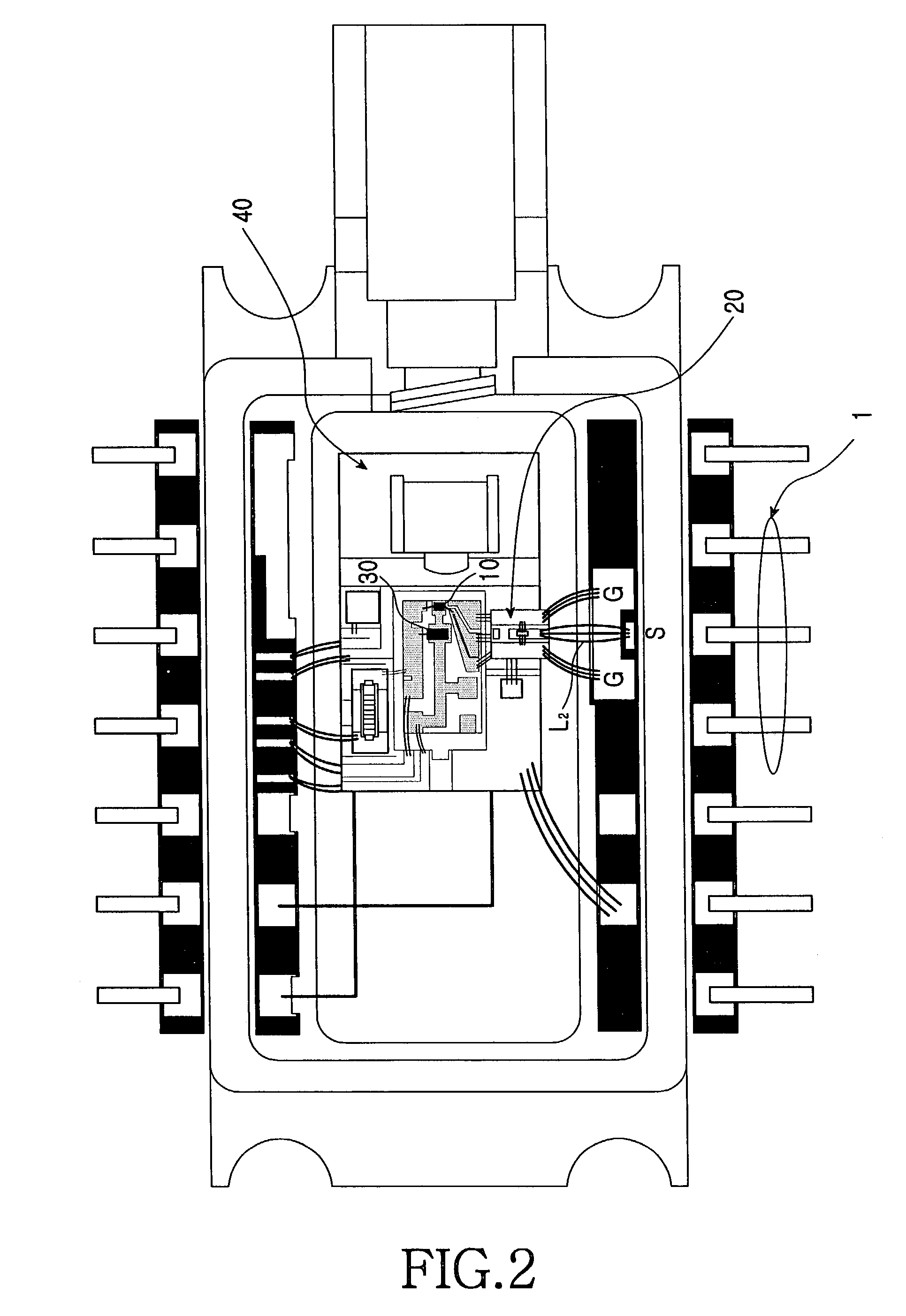
[0024]FIG. 2 is a plane diagram of the laser module according to the embodiment of the present invention. As shown in FI...


PUM


Abstract

A laser module for transmitting / receiving digital signals using a laser diode as an optical source is disclosed. The input end of the laser module is provided with a low pass filter, such that the low pass filter makes a 3 dB bandwidth of frequency response transferred from the input pins to the laser diode to be equal or less than the on-state relaxation oscillation frequency of the laser diode, wherein the overshoot is minimized by adjusting a relative amount of the frequency component input to the laser diode.

Description

CLIAM OF PRIORITY[0001]This application claims priority to an application entitled “LASER MODULE,” filed in the Korean Intellectual Property Office on Jun. 3, 2002 and assigned Serial No. 2002-31177, the contents of which are hereby incorporated by reference.BACKGROUND OF THE INVENTION[0002]1. Field of the Invention[0003]The present invention relates to a laser module and more particular to a laser module used as a light source for sending / receiving digital signals.[0004]2. Description of the Related Art[0005]A light transmission module is capable of transforming an electrical signal to an optical signal of a desired wavelength through a semiconductor laser. A light reception module is capable of transforming the optical signal to the electrical signal.[0006]In order to transmit digital signals of Non Return to Zero (NRZ), Return to Zero (RZ), etc., a laser diode—such as a 2.5 Gbps Distributed Feedback-Laser Diode (DFB-LD) module or a 10 Gbps DFB-LD module—is used as a light source....

Claims


Application Information

Patent Timeline
Patent Type & Authority Patents(United States)
IPC IPC(8): H01S3/00H01S3/13H01S5/026H01S5/02H01S5/022H01S5/042H01S5/06
CPCH01S5/02276H01S5/02216H01S5/02248H01S5/02284H01S5/0427H01L2224/49111H01L2924/19107H01L2224/48091H01L2224/49175H01L2924/00014H01S5/02345H01S5/02325H01S5/02251H01S5/06
Inventor PARK, SUNG-SOO
Owner SAMSUNG ELECTRONICS CO LTD
Why Eureka
Try Eureka