
Bidirectional pedal assembly

a pedal assembly and bi-directional technology, applied in the direction of mechanical control devices, process and machine control, instruments, etc., can solve the problems of unnecessary throttle demand, deficient throttle demand, oscillation of the neutral position, etc., and achieve the effect of preventing oscillation

Active Publication Date: 2019-07-16
KONGSBERG POWER PROD SYST I
View PDF40 Cites 1 Cited by
  • Summary
  • Abstract
  • Description
  • Claims
  • Application Information

AI Technical Summary

Benefits of technology

The present patent is aimed at providing an improved bidirectional pedal assembly for a vehicle that returns to its neutral position without causing oscillation or overshooting the position. The assembly includes a support, a pivot shaft, and a pedal pivotally coupled to the shaft. A handle is operably connected to the pedal and pivots along with it. A biasing member is mounted within the support to continuously bias the pedal to its neutral position. A control mechanism is coupled to the support and the pedal to retard its pivotal movement as it returns from its operational positions to the neutral position.

Problems solved by technology

The arrangement can undesirably result in oscillations about the neutral position, particularly upon increasing the size and / or weight of the pedal assembly, and / or connecting structures to the pedal assembly that increase torque about the fixed base.
Such signals can result in unnecessary throttle demand or deficient throttle demand to the vehicle.

Method used


Image

  • Bidirectional pedal assembly
  • Bidirectional pedal assembly
  • Bidirectional pedal assembly

Examples


Embodiment Construction

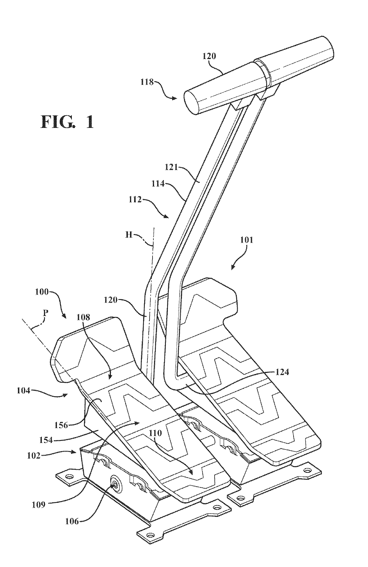
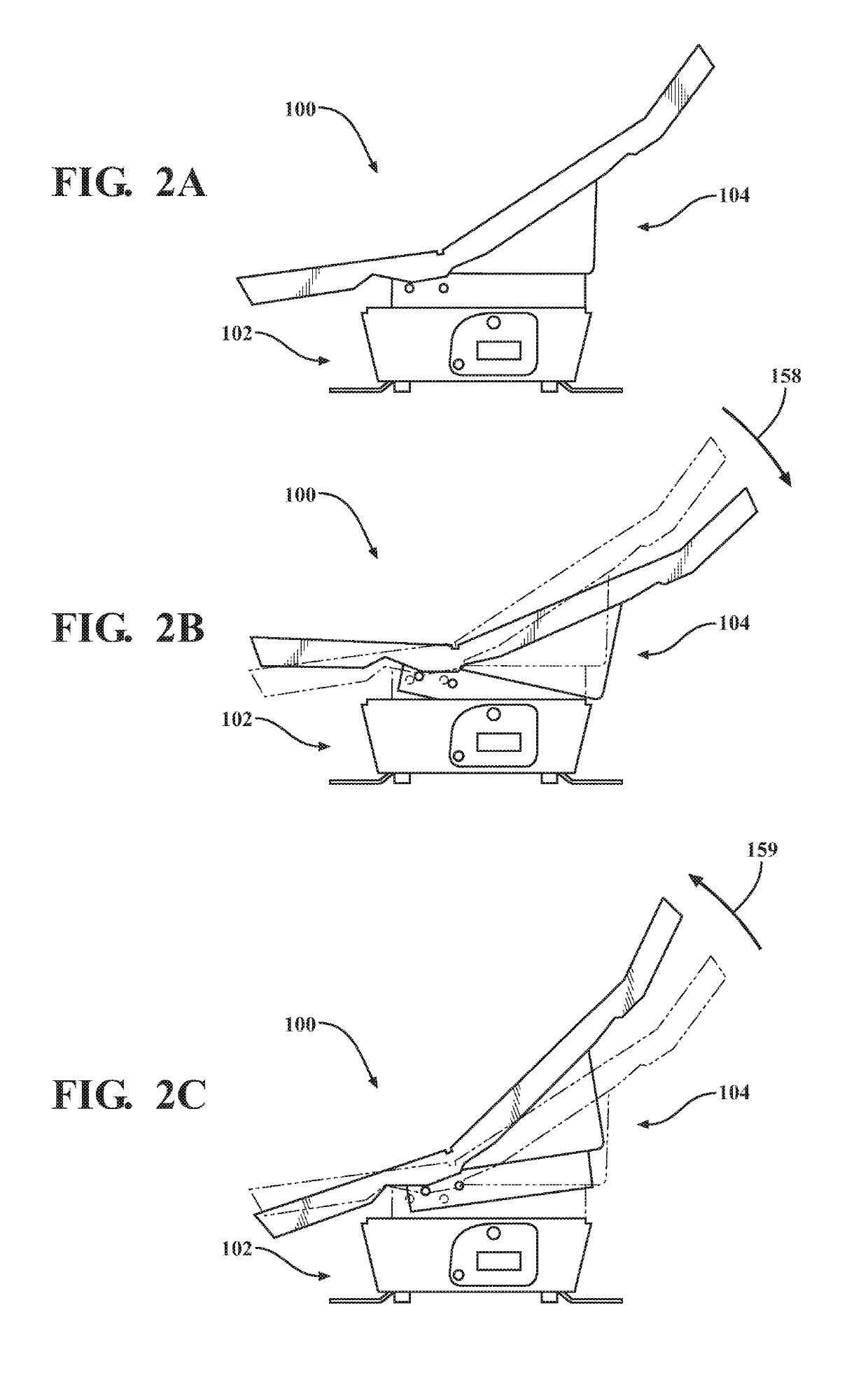
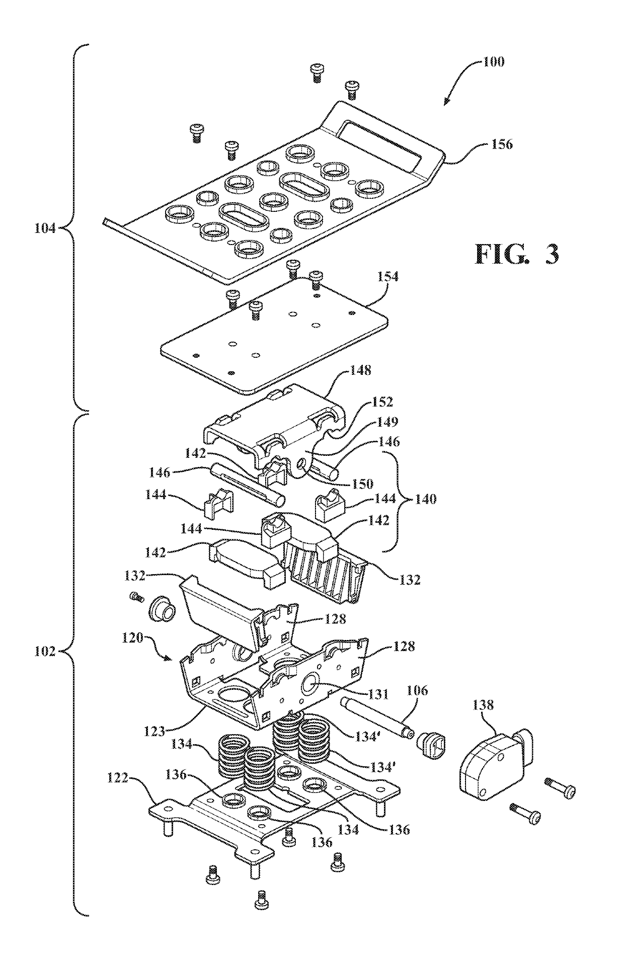
[0036]Referring to FIG. 1, a pair of bidirectional pedal assemblies 100, 101 according to an exemplary embodiment is illustrated. FIG. 1 illustrates two bidirectional pedal assemblies 100, 101 positioned in a side-by-side configuration. In a preferred application, one bidirectional pedal assembly 100 controls one operation and / or component of a vehicle, while the other bidirectional pedal assembly 101 controls another operation and / or component of the vehicle. For example, with a continuous tracked tractor (e.g., bulldozer or other crawler), the left bidirectional pedal assembly 100 (from a perspective of an operator) can control the left track whereas the right bidirectional pedal assembly 101 can control the right track. Other wheeled heavy equipment machines such as a front loader can be similarly controlled by the left and right bidirectional pedal assemblies 100, 101, as disclosed herein, to provide for low turning radius or “zero turning radius.” Other applications are also co...


PUM


Abstract

A bidirectional pedal assembly for a vehicle. The assembly includes a support mounted on the vehicle and a pedal pivotally coupled to the support about a pivot shaft. The pedal pivots between a neutral position and first and second operational positions. A biasing member is mounted within the support and continuously biases the pedal to the neutral position. A control mechanism is coupled to the support and the pedal to retard pivotal movement of the pedal as the pedal returns from the operational positions to the neutral position. A handle can be coupled to the pedal and pivot concurrently with the pedal. A frictional mechanism can be disposed within the support and provide increasing resistance as the pedal moves increasingly away from the neutral position. The biasing mechanism, frictional mechanism, and / or control mechanism are configured to force the pedal to the neutral position with no overshoot within a predetermined period.

Description

CROSS-REFERENCE TO RELATED APPLICATIONS[0001]The present application is the National Stage of International Patent Application No. PCT / US2016 / 038965, filed on Jun. 23, 2016, which claims priority to and all the benefits of U.S. Provisional Patent Application No. 62 / 183,432, filed on Jun. 23, 2015, each of which is hereby expressly incorporated by reference in its entirety.FIELD OF THE DISCLOSURE[0002]The present disclosure relates to a bidirectional pedal assembly for a vehicle.BACKGROUND OF THE DISCLOSURE[0003]Bidirectional pedal systems are often used in vehicular applications (for example trucks and utility vehicles) to control vehicle operations. Such pedal systems typically include a bidirectional pedal assembly (also known as an over-center rocker pedal) configured to move relative to a fixed base between first and second operational positions opposite a neutral position. Upon release of an applied force by an operator, the pedal assembly returns to the neutral position under ...

Claims


Application Information

Patent Timeline
Patent Type & Authority Patents(United States)
IPC IPC(8): G05G1/44G05G1/445G05G5/03G05G1/487G05G5/05
CPCG05G1/445G05G1/44G05G5/05G05G5/03G05G1/487
Inventor POIRIER, RONDABUGAMELLI, ANTHONYHENGST, AARONHENRIKSON, JESSE
Owner KONGSBERG POWER PROD SYST I
Learn More