Thermal resistance heater

a heater and thermal insulation technology, applied in the field of thermal insulation heaters, can solve the problems of tumors that cannot be completely inactivated or controlled to death, tumors that cannot be completely inactivated, and large temperature differences inside the tumor, so as to achieve precise temperature control, minimize overshoot, and stable and precise data

Inactive Publication Date: 2020-11-12
YU XUELI
View PDF0 Cites 0 Cited by
  • Summary
  • Abstract
  • Description
  • Claims
  • Application Information

AI Technical Summary

Benefits of technology

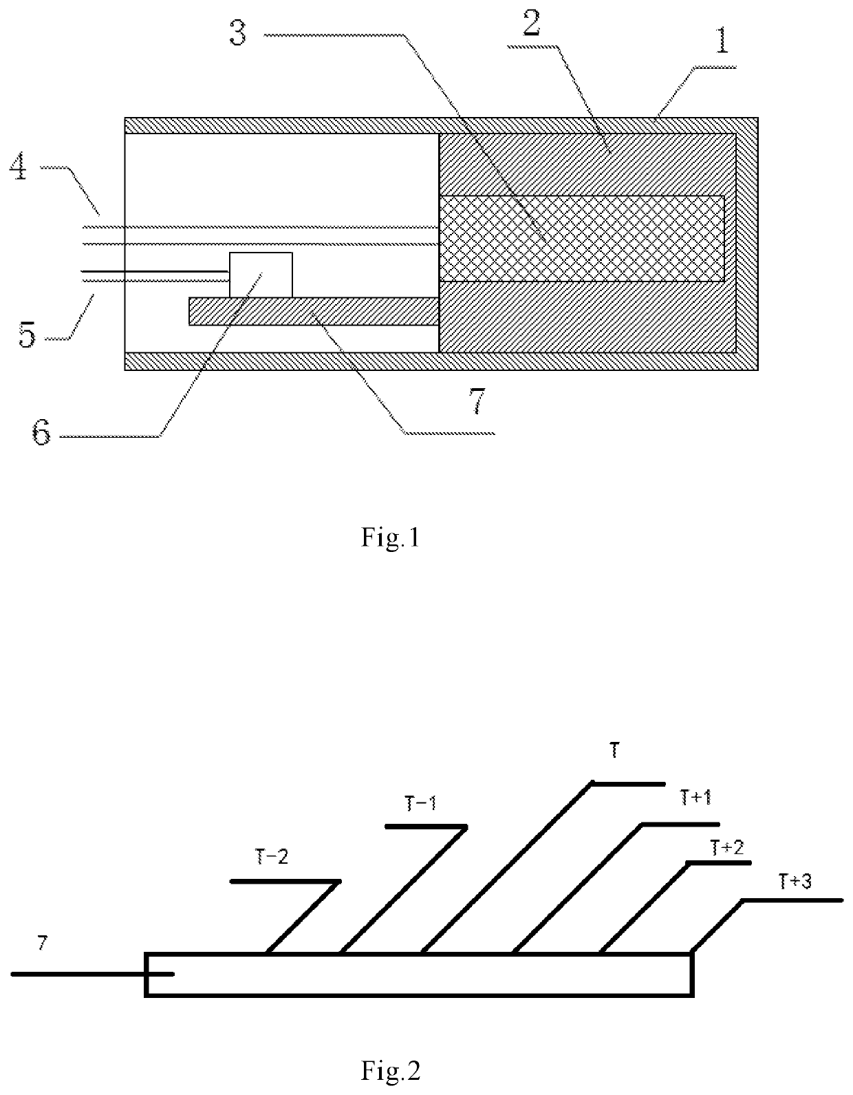
[0020](1) The temperature sensed by the temperature sensor can be configured to be the same with a surface temperature of the heater, or allow an error there-between within a threshold by adjusting a fixed position where the temperature sensor disposed on the thermal-conduction compensation arm. Therefore, the controller can precisely control the surface temperature of heater.
[0021](2) In the disclosure, the tumor tissue is inactivated and ablated by heating the thermal resistance. The controller can precisely control the surface temperature when the temperature sensor disposed on the thermal-conduction compensation arm is used to sense the temperature. The procedure for inactivation and apoptosis of tumor can therefore be controlled for preventing the patient's normal tissues or organs from being destroyed.
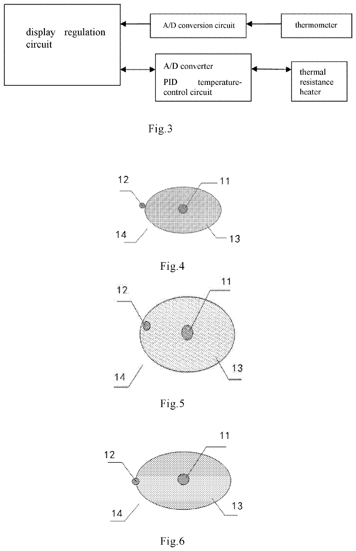
[0022](3) Since the tumor hyperthermia of the disclosure adopts a thermal resistance to heat the tumor tissue via a means of thermal conduction, the internal temperatures of the tumor tissue appear to be a gradient distribution. According to the gradient distribution of the temperatures, the temperature of the tissue near a thermal resistance heater is high and the temperature of the tissue being away from the thermal resistance heater is low. There is no exception to any tumor tissue structure. When a temperature value of a thermometer that is placed at an intersectional area between the tumor tissue and normal tissue reaches a valid temperature, it indicates that the temperatures of the entire tumor tissue are not lower than the valid temperature. Therefore, when the temperatures generated by thermometer 2 placed at the intersectional area between the tumor tissue and the normal tissue can be stabilized within 43° C. to 45° C. for a while, the method for tumor hyperthermia can completely inactivate the tumor tissue without harming the normal human tissue.
[0023](4) The data generated by the temperature-controllable thermal resistance heater and the thermometer is real, reliable and continuous since the thermal resistance heater of the disclosure does not produce electromagnetic radiation and also not interfere the temperature sensor.
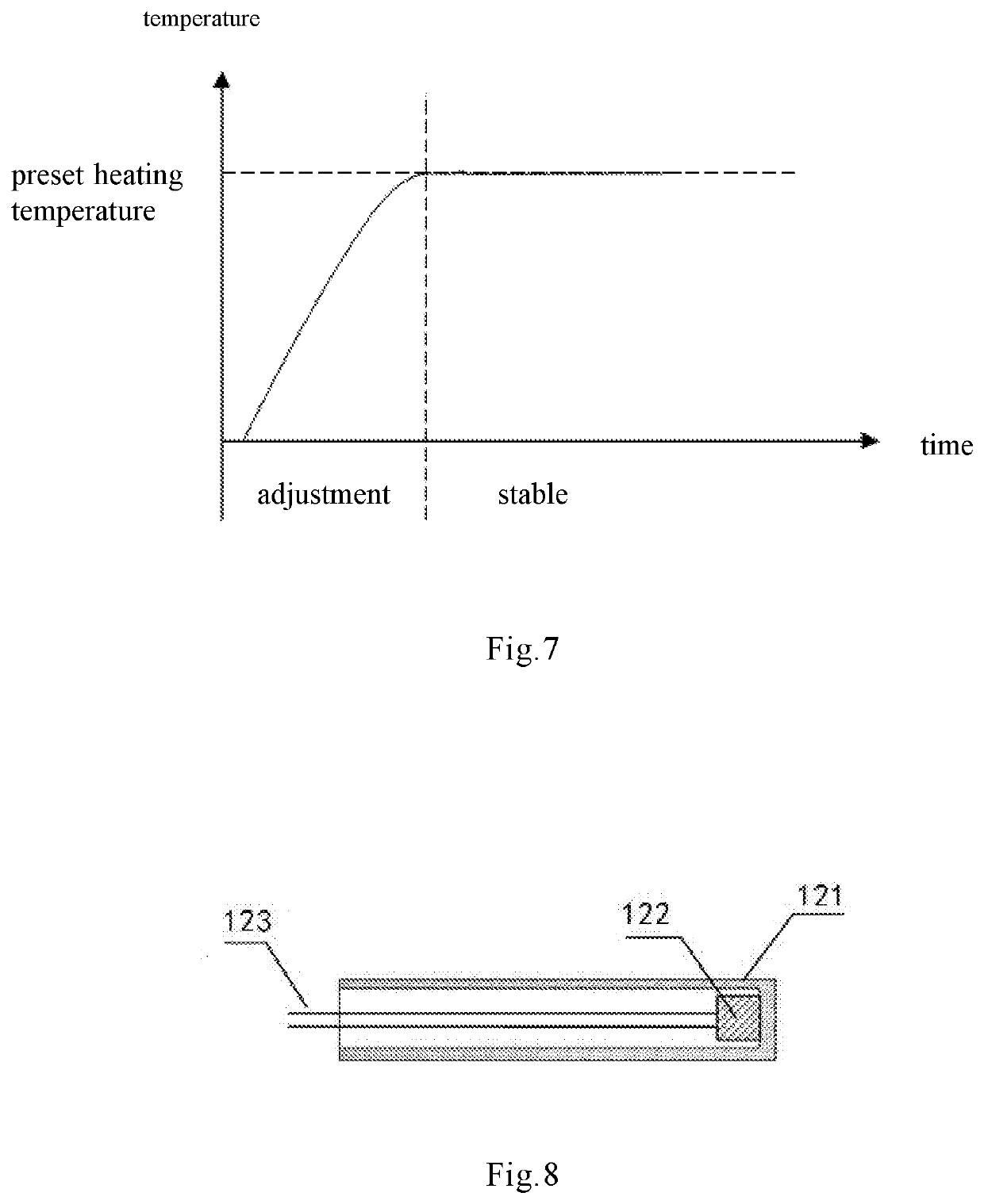
[0024](5) A PID temperature-control circuit can be used in the thermal resistance heater of the disclosure. The PID temperature-control circuit makes the temperature-controllable thermal resistance heater 1 generating stable and precise data. Therefore, in the process of controlling temperature, it achieves that the tumor hyperthermia has minimized overshoot, precise temperature control, and safe and reliable hyperthermia procedure.

Problems solved by technology

Since the tumor tissue is a combination of multiple structures, the temperatures heated by the radio frequency or electromagnetic waves over the entire tumor issue are uneven, and the temperature differences inside the tumor are large.
Otherwise, the tumor cannot be inactivated completely or controlled to death.
Furthermore, the heat may harm the normal tissues or organs of the patient.
However, the position where the temperature sensor is disposed on the thermal resistance heater affects an accuracy of temperature measurement.
If the temperature sensor is disposed on a surface of the thermal resistance heater and directly contacts with the tumor tissue, some problems may occur as follows.
Secondly, if the point to be measured by the temperature sensor is at a region with poor heat-dissipation, the temperature of the region with poor heat-dissipation is higher than other regions with good heat-dissipation since the heat of the point may not be transferred efficiently.

Method used


Image

  • Thermal resistance heater
  • Thermal resistance heater
  • Thermal resistance heater

Examples


Embodiment Construction

[0035]The present disclosure is more particularly described in the following examples that are intended as illustrative only since numerous modifications and variations therein will be apparent to those skilled in the art. Like numbers in the drawings indicate like components throughout the views. As used in the description herein and throughout the claims that follow, unless the context clearly dictates otherwise, the meaning of “a”, “an”, and “the” includes plural reference, and the meaning of “in” includes “in” and “on”. Titles or subtitles can be used herein for the convenience of a reader, which shall have no influence on the scope of the present disclosure.

[0036]The terms used herein generally have their ordinary meanings in the art. In the case of conflict, the present document, including any definitions given herein, will prevail. The same thing can be expressed in more than one way. Alternative language and synonyms can be used for any term(s) discussed herein, and no speci...


PUM


Abstract

A thermal resistance heater with a thermal conductive shell that is used to contact with tumor tissues and conduct heat therefor is provided. A thermal resistance is disposed inside the thermal conductive shell and is self-heated via current. The thermal energy is converted from the electrical energy according to Joule's Law. The heater includes a heat radiator disposed inside the shell and is used to disperse the heat generated by the thermal resistance and conduct the heat to the shell evenly. A thermal-conduction compensation arm and the heat radiator are contacted for achieving that a temperature of the shell is the same with a specific place or an error there-between is within a threshold. A temperature sensor is used to obtain a surface average temperature of the conductive shell by collecting temperatures over the thermal-conduction compensation arm. By adjusting position the temperature sensor is disposed on thermal-conduction compensation arm, the temperature sensed by the temperature sensor can be the same with a surface temperature of a heating zone of the shell or an error there-between is within a threshold. It achieves that a controller precisely controls a surface temperature of heater.

Description

FIELD OF THE DISCLOSURE[0001]The disclosure is generally related to a thermal resistance heater, and more particularly to a thermal resistance heater applied for treatment of tumor.BACKGROUND OF THE DISCLOSURE[0002]The clinical equipment for tumor hyperthermia is such as a radio-frequency hyperthermia device or an electromagnetic wave hyperthermia device for tumor treatment. The conventional equipment heats the tumor tissue with electromagnetic waves. The principle is that the human tissues will be heated by absorbing the electromagnetic waves. The human tissues convert the absorbed electromagnetic waves to heat. The electric-thermal conversion is not only related to the intensity of electromagnetic waves, but also to structure and dielectric constant of the human tissues. Since the tumor tissue is a combination of multiple structures, the temperatures heated by the radio frequency or electromagnetic waves over the entire tumor issue are uneven, and the temperature differences insid...

Claims


Application Information

Patent Timeline
Patent Type & Authority Applications(United States)
IPC IPC(8): A61B18/08H05B1/02H05B3/10A61F7/00
CPCA61F2007/0088A61B18/08H05B1/025A61B2018/00791A61F2007/0071A61F7/007A61F2007/0096H05B3/10A61B2018/00577A61B18/12A61B18/14A61B2018/00714
Inventor YU, XUELI
Owner YU XUELI
Why Eureka
Try Eureka