
Ir spectrometry cell with temperature control means

a technology of ir spectrometry and sample cell, which is applied in the direction of spectrometry/spectrophotometry/monochromator, optical radiation measurement, instruments, etc., can solve the problems of temperature increase, temperature increase, and heat transfer from heat resistors, through metal heating blocks, to the temperature sensor takes some time, so as to improve the temperature stability of the sample cell

Active Publication Date: 2014-07-17
PERKINELMER U S LLC
View PDF6 Cites 1 Cited by
  • Summary
  • Abstract
  • Description
  • Claims
  • Application Information

AI Technical Summary

Benefits of technology

The invention provides a sample cell with improved temperature stability. The use of a heating foil instead of metal resistors has two main advantages: it is close to the liquid to be analyzed and can be designed in a flexible shape to provide a more evenly distributed heat supply. Additionally, the cell includes a temperature sensor close to the heating element, which ensures accurate temperature control and reduces overshoot. These improvements lead to reduced temperature fluctuations and improved reproducibility of the sample temperature, making it important for reliably analyzing multiple samples.

Problems solved by technology

One of the disadvantages of this setup is that the temperature control loop works too slowly.
This leads, for example, to overshoot.
When the temperature sensor measures a too low temperature, the heat resistors heat the heating block and the temperature increases over time.
The transfer of heat from the heat resistors, through the metal heating block, to the temperature sensor does however take some time.
Even when adapting the temperature control loop in order to compensate for this overshoot, it is not possible to keep the sample at the desired temperature.
However, the use of this single heat source in the larger metal block will always lead to fluctuating temperatures.

Method used


Image

  • Ir spectrometry cell with temperature control means
  • Ir spectrometry cell with temperature control means
  • Ir spectrometry cell with temperature control means

Examples


Embodiment Construction

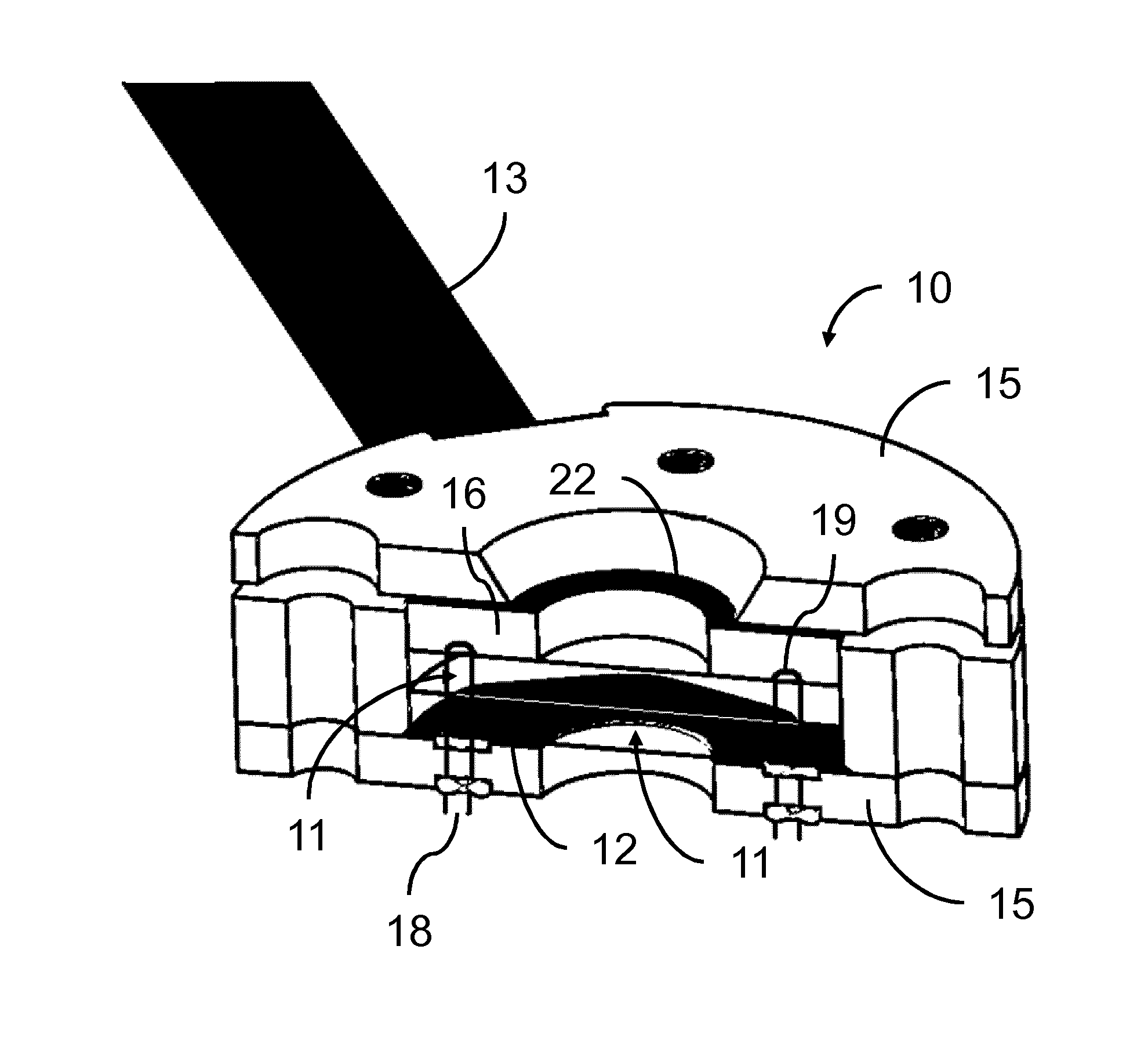
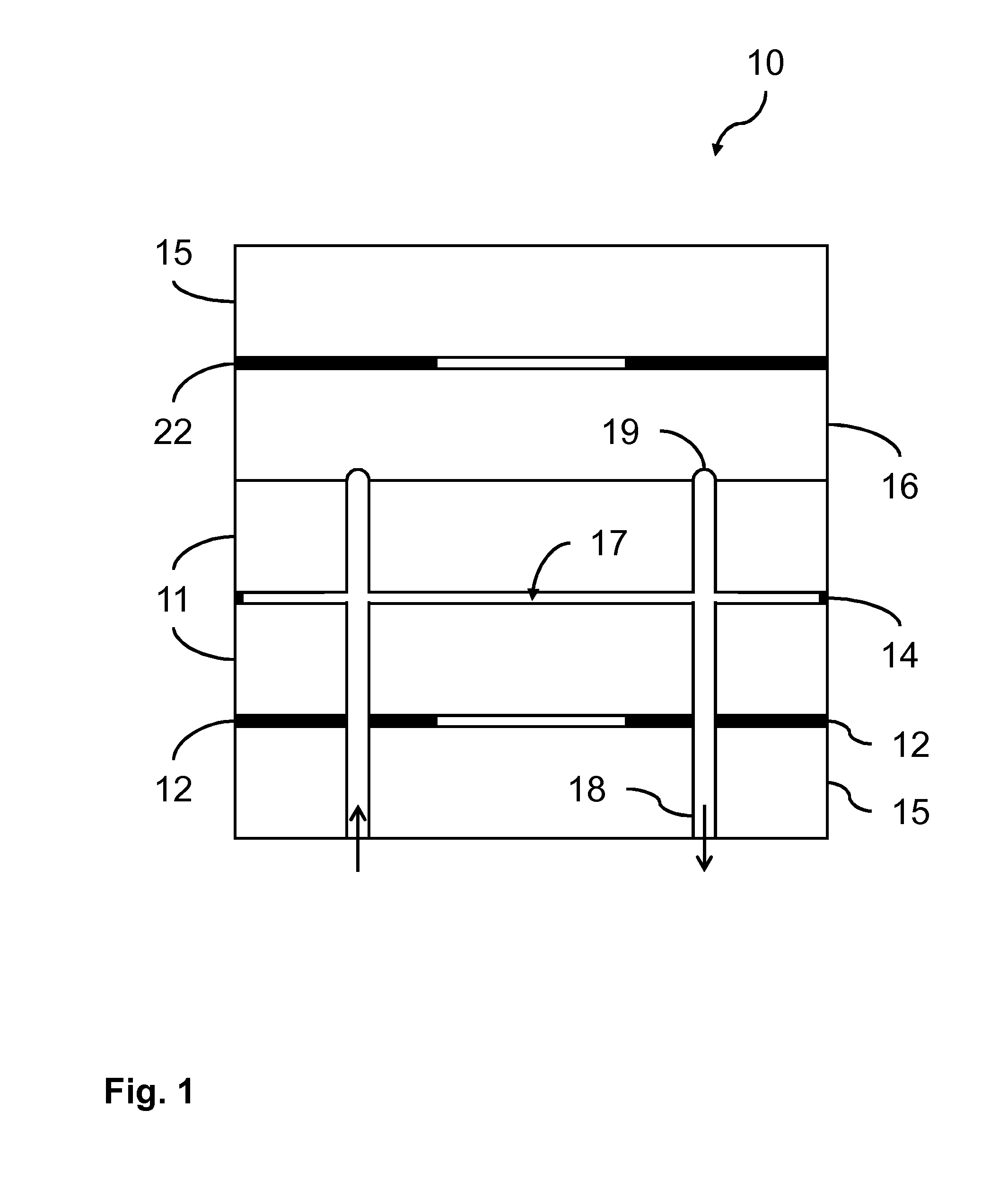
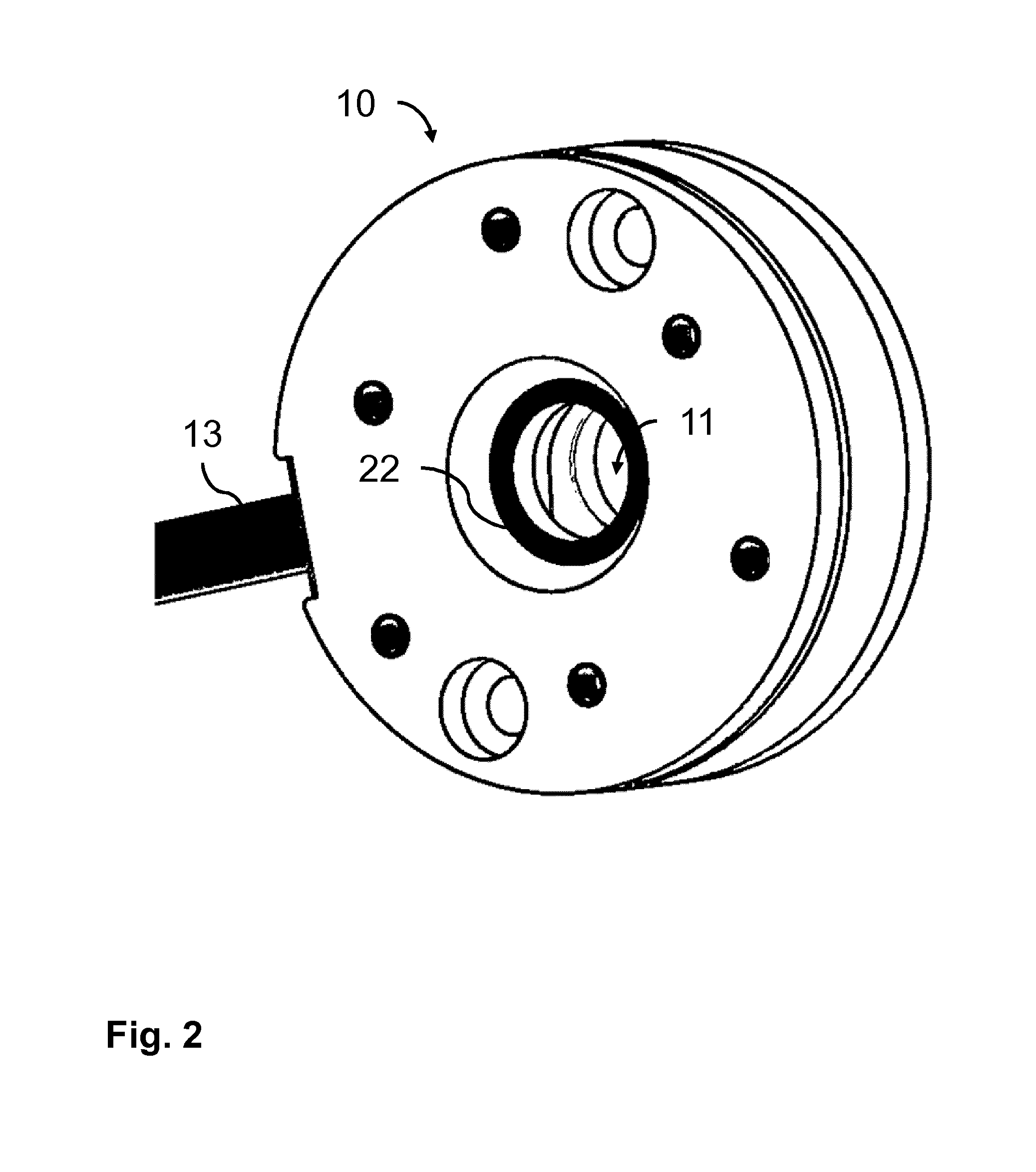
[0019]FIG. 1 schematically shows a cross section of a sample cell 10 according to the invention. The sample cell 10 comprises two transparent plates 11, separated by spacers 14. In, e.g., milk analysis by IR spectrophotometry the spacers usually provide a 20-40 μm (micrometer) wide cavity 17 between the two substantially parallel plates 11. The transparent plates 11 may, e.g., be made of glass, crystalline calcium fluoride (CaF2) or transparent plastics. Also diamond may be used for producing the sample cell 10. In order to be suitable for IR spectrophotometry, the plates 11 only have to be transparent for the IR wavelengths used for the IR spectrophotometry, but it may be practical to select a material that is also transparent for visible light. If the user can look into the cavity 17, it is possible to visually inspect the analyzed liquid. If the sample cell is also used for analysis methods involving light of a different wavelength, the transparent plates 11 also have to be trans...


PUM


Abstract

A sample cell for IR spectrophotometric analysis of a liquid sample is provided. The sample cell comprises two substantially parallel transparent plates enclosing a cavity for holding the liquid sample, and a temperature control loop for controlling a temperature of the liquid sample in the cavity. The temperature control loop comprises at least one temperature sensor for measuring a temperature in or close to the cavity, at least one heating element for increasing a temperature of the liquid sample, and control means, coupled to the temperature sensor and the heating element for controlling the heating element in dependence of the temperature in or close to the cavity. The heating element comprises at least one heating foil which is attached to or thermally coupled to a first one of the transparent plates in such a way to allow an IR light beam to pass through the transparent plates and the cavity without being hindered by the heating foil.

Description

FIELD OF THE INVENTION[0001]This invention relates to a sample cell for IR spectrophotometric analysis of a liquid sample. The sample cell comprises two substantially parallel transparent plates enclosing a cavity for holding the liquid sample and a temperature control loop for controlling a temperature of the liquid sample in the cavity. The temperature control loop comprises at least one temperature sensor for measuring a temperature in or close to the cavity, at least one heating element for increasing a temperature of the liquid sample, and control means, coupled to the temperature sensor and the heating element for controlling the heating element in dependence of the temperature in or close to the cavity.[0002]This invention further relates to the heating element for use in such a sample cell.BACKGROUND OF THE INVENTION[0003]Such a sample cell is, e.g., known from U.S. Pat. No. 4,415,809 in which an electro-optical apparatus for measurement of fat, protein, lactose and water or...

Claims


Application Information

Patent Timeline
Patent Type & Authority Applications(United States)
IPC IPC(8): G01J3/02G01J3/28
CPCG01J3/28G01J3/0267G01N33/04G01N21/0332G01N21/05G01N21/3577G01N2021/0346
Inventor TERPSTRA, ANNE GERBEN
Owner PERKINELMER U S LLC
Learn More