Closed-loop magnetic sensor system

a closed-loop, magnetic sensor technology, applied in the field of sensors, can solve the problems of significant amplitude and temperature dependence, permanent remanence, and the inability to operate continuously, so as to reduce offset current, improve operating characteristics, and reduce cost

Inactive Publication Date: 2007-05-24
HONEYWELL INT INC
View PDF17 Cites 48 Cited by
  • Summary
  • Abstract
  • Description
  • Claims
  • Application Information

AI Technical Summary

Benefits of technology

[0015] It is a further aspect of the present invention to provide for a magnetic sensor system at lower cost.
[0016] It is yet a further aspect to provide a closed loop magnetic current sensor system having improved operating characteristics including reduced offset current, increased temperature stability and improved bandwidth.

Problems solved by technology

Such Hall current sensors are sensitive to short current peaks in the circuit because the hysterisis properties of the magnetic core cause static magnetization in the core which results in a permanent remanence.
Closed loop current sensors of the aforementioned types suffer from several major drawbacks.
Firstly, there is an inevitable offset current, associated with the effects of the magnetic core, whose amplitude and temperature dependence are subject to significant fluctuations.
There are many disadvantages of a ferrous core, such as for example, core losses, limited bandwidth, non-linearity, thermal instability, bulk and cost.
The core losses in conventional current sensors result in a temperature rise thereby further contributing to non-linearity and current off-set fluctuation.
The bandwidth in a ferrous core is also limited by the core losses.
Yet another drawback of the aforementioned magnetic current sensors is that demand for such sensors using magnetic cores with larger cross sectional area is substantially increasing the dimension and weight of the magnetic sensor and the complexity and cost of the sensor manufacturing process.

Method used


Image

  • Closed-loop magnetic sensor system
  • Closed-loop magnetic sensor system
  • Closed-loop magnetic sensor system

Examples


Embodiment Construction

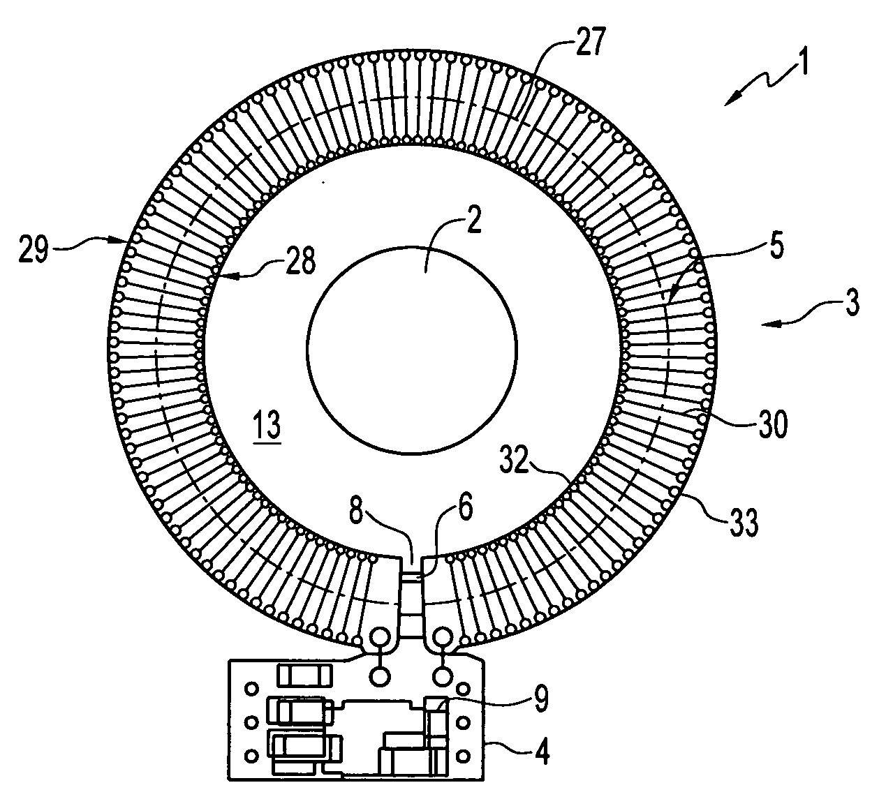
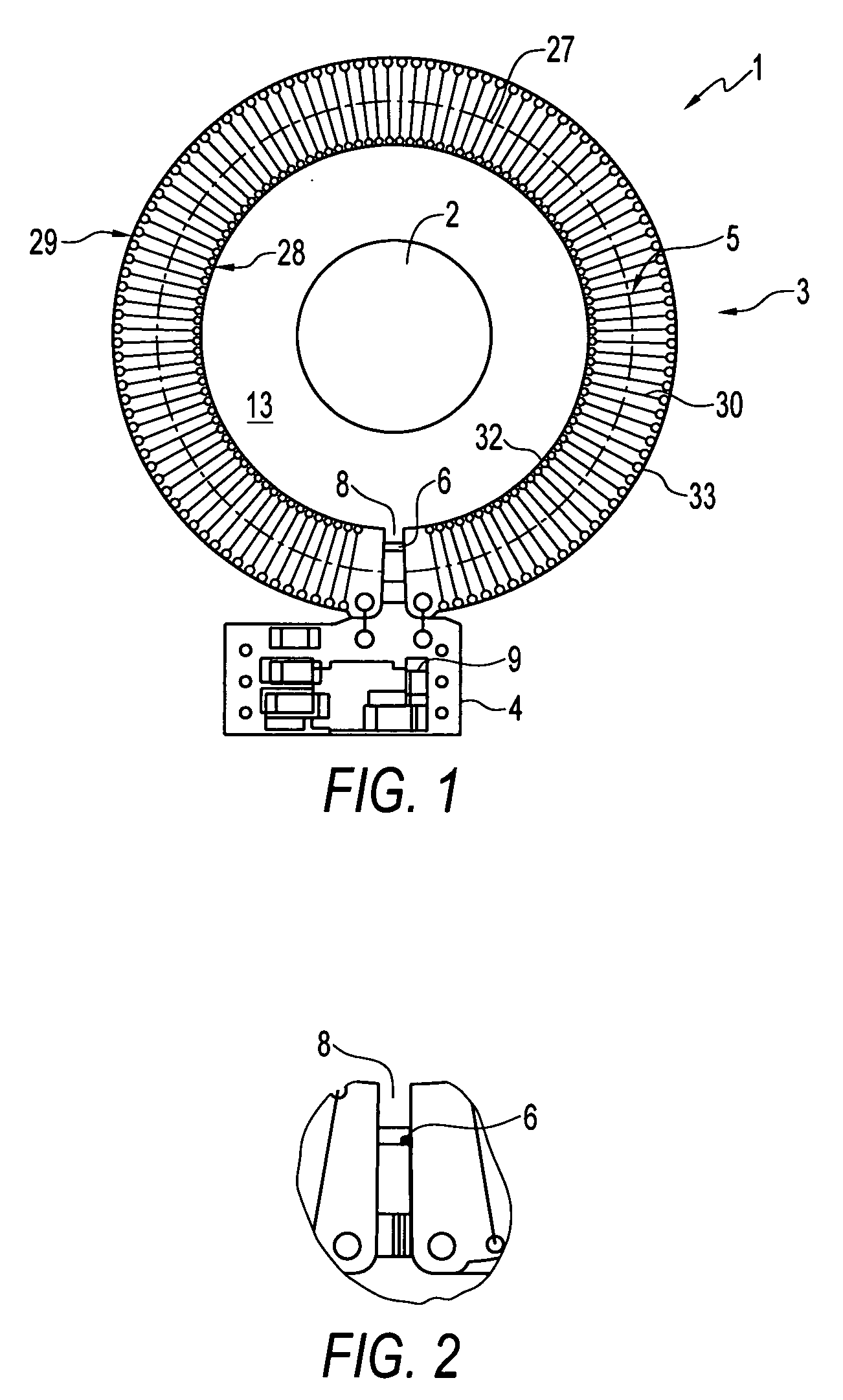
[0041] Referring to FIG. 1 of the accompanying drawings, which illustrates a plan view of the closed loop magnetic sensor system according to a preferred embodiment, the magnetic sensor system 1 has a magnetic sensor 6 for sensing an input magnetic field generated by a magnetic source 2, and a compensating current carrying conductor 5, magnetically coupled to the magnetic sensor 6, for generating a compensating magnetic field at the magnetic field sensor.

[0042] As will be described in more detail below, the compensating conductor 5 is arranged as a series of coils embedded in a dielectric medium. Arranging the compensating conductor 5 in or on a dielectric medium advantageously increases the Galvanic isolation between the compensating conductor 5 and the magnetic source 2, thereby increasing the breakdown voltage between the magnetic source 2 and compensating conductor 5, and enabling the magnetic senor 6 to sense the input magnetic field with a high sensitivity without requiring t...


PUM

PropertyMeasurementUnit
magnetic fieldaaaaaaaaaa
conductiveaaaaaaaaaa
magnetic fluxaaaaaaaaaa

Abstract

A closed loop magnetic sensor system for measuring an input magnetic field from a magnetic field source has a compensation circuit, which can be for example a printed wire board, and a magnetic sensor, such as a Magnetoresistive (MR) sensor, for measuring an input magnetic field. Preferably, the magnetic sensor is magnetically coupled to the compensation circuit by arranging the magnetic sensor in an air gap provided in the compensation circuit. The compensation circuit has a compensating conductor, arranged on or in a dielectric medium, which can be configured as a plurality of nested coils. Electrical control circuitry, electrically, coupled to the magnetic sensor and compensating conductor, is adapted and arranged to drive a feedback current through the compensating conductor according to the output of the magnetic sensor such that the input magnetic field is substantially compensated at the magnetic sensor. The magnetic system can serve as current sensor for sensing current through a primary conductor.

Description

TECHNICAL FIELD [0001] Embodiments are generally related to sensors and applications thereof and, more particularly, to magnetic field sensors for measuring magnetic flux. Embodiments are additionally related to magnetic sensor systems for measuring electrical current flowing in a conductor by sensing the magnetic field generated by the conductor. Additionally, embodiments are related to closed-loop magnetic sensor systems and compensation circuits employed in such systems. BACKGROUND [0002] Conventional magnetic sensors for measuring current through a conductor include a magnetic circuit in the form of a core of magnetic material provided with an air-gap in which a magnetic field sensor, such as, for example, a Hall Effect sensor, is located. The conductor carrying the current to be measured, often called a “primary conductor”, passes through the magnetic circuit one or several times. Typically, such sensors are used in applications in which relatively large electrical currents are...

Claims


Application Information

Patent Timeline
Patent Type & Authority Applications(United States)
IPC IPC(8): G01N27/72
CPCG01R15/205G01R15/207
Inventor MUNIRAJU, RAGHAVENDRAREDDY, GANGI RAJULASADASIVAN, SARAVANANTELI, BASAVARAJA M.VEEDU, SUDHEER PULIKKARA
Owner HONEYWELL INT INC
Why Eureka
Try Eureka