Optical co2 and combined o2/co2 sensors

a technology of oxygen sensor and optical co2 is applied in the field of improved carbon dioxide and oxygen sensor, which can solve the problems of low mechanical strength of a polymer, affecting the calibration of the sensor, and less reliable in moist environments. achieve the effect of high wavelength tail of led emission and good temperature stability

Inactive Publication Date: 2006-11-16
INVENT CENT THE
View PDF0 Cites 48 Cited by
  • Summary
  • Abstract
  • Description
  • Claims
  • Application Information

AI Technical Summary

Benefits of technology

[0030] The optical reader may comprise a probe with a transparent window, a fibre optic bundle with collimating optics both that interrogate the sensor non-invasively, or an invasive fibre tip encompassing the sensor on / in the fibre. There are two LEDs; the first is the excitation source and the second is the reference. The excitation source is a blue LED (Nichia, NSPB500) and is chosen for its relatively stable temperature characteristics which match those of the reference LED. The detector is a silicon photodiode (Hamamatsu, S1223), which also exhibits good temperature stability. Modulated light from the blue LED is filtered using a blue glass bandpass filter (OF1: Schott, BG12) of thickness 2 mm in order to eliminate the high wavelength tail of the LED emission. The phase-shifted fluorescence from the sensor film is incident on the photodiode after passing through an optical long-pass filter (OF3: LEE-gel filter 135), to separate the excitation light from the emission. The second LED (Hewlett Packard, HLMA-KL00) is part of an internal dual referencing scheme. This reference LED emits at 590 nm and is filtered by a bandpass filter (OF3: Schott, BG39). This LED is in the same spectral range as the fluorescence (610 nm), and has been carefully selected to match the blue excitation LED in terms of switching time and temperature characteristics. Spurious phase shifts as a function of temperature and other fluctuations are eliminated by this dual referencing. The detection electronics measure the variation in phase angle with oxygen or carbon dioxide concentration. The phase angle is the measured phase difference between the sinusoidally modulated reference excitation signal and the resultant fluorescence signal which is phase shifted with respect to the reference signal. The fluorescence signal changes with analyte concentration. The phase signals (reference and excitation) are fed into a phase detector and the phase difference is measured.

Problems solved by technology

One problem associated with this type of sensor is that because the sensor is formulated in a polymer matrix, the polymer will swell in a moist environment, which affects the calibration of the sensor and makes the sensor less reliable in moist environments.
Furthermore, mechanical strength of a polymer is low in that the material is a rubbery type material rather than a rigid glass-like material like sol-gel, and optical transparency can be poor as polymeric films can be cloudy.
Currently used methods of checking the integrity of packages and the possible contamination of sterilised products involve destructive sampling in which a proportion of the packages are opened and tested for damage to the packaging for microbial contamination.
However, this method only tests a small proportion of the packages and damaged packages could be present in the much larger proportion of packages not tested.
Furthermore, the method destroys packages which may well have been intact and is therefore quite wasteful of both packages and their contents.
As this is a destructive method, only a small percentage of the packages can be tested and so 100% quality control is not possible.
If a package is found to be leaking, what follows is a time consuming and costly process of back-checking and repacking.
The problem with this sensor is that it only measures oxygen levels, when in fact it is normally a fall in O2 levels and a concomitant rise in CO2 levels which is indicative of microbial spoilage.
Additionally, the sticker, which is in contact with the package contents, could become unstuck and possibly damage or otherwise interfere with the contents.
Many of the optical-based sensors for food packaging that have been made available are visual indicators in the form of inserts that also contain scavenging capability, and are not very accurate.

Method used


Image

  • Optical co2 and combined o2/co2 sensors
  • Optical co2 and combined o2/co2 sensors
  • Optical co2 and combined o2/co2 sensors

Examples


Embodiment Construction

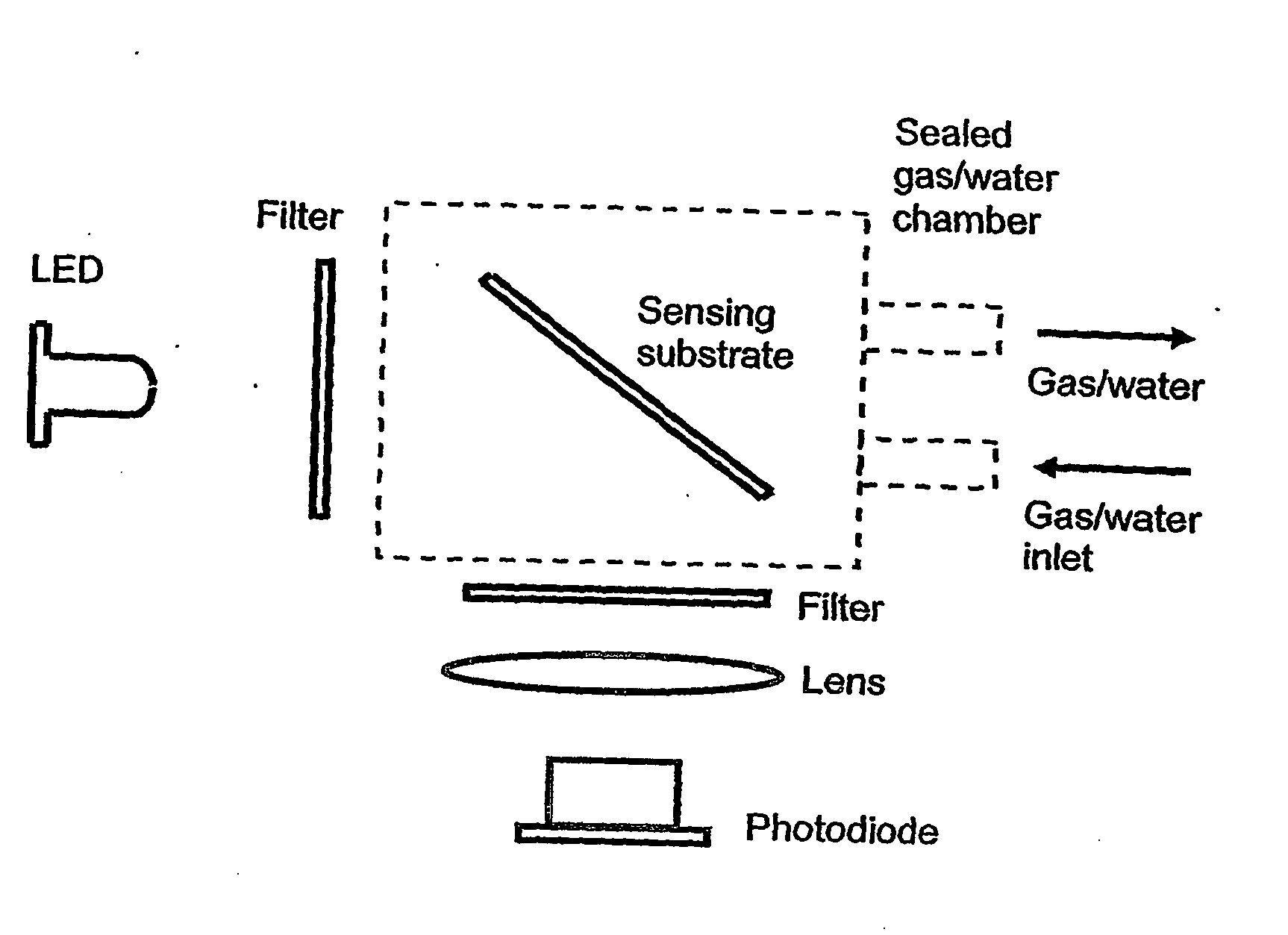
[0045] Optical sensor films with associated scanner to confirm the integrity of the package and hence freshness of packaged food in a non-destructive manner. Sensor films have been developed for oxygen and carbon dioxide. They are fluorescent and their fluorescence changes with exposure to the specific gas concentration. The films can be deposited on a solid or a flexible substrate using standard printing techniques e.g. spin coating, screen printing etc. The films are excited by a common excitation source i.e. a blue LED, and the resultant fluorescence is detected using a silicon photodiode. These optoelectronic components along with relevant ICs and electronic components can be housed in an optical reader or scanner device capable of interrogating the sensor films.

[0046] Fluorescent sensors for oxygen and carbon dioxide have been developed. Both of these sensors can be scanned using an optical reader, which will give a readout of the concentration of oxygen and carbon dioxide in ...


PUM

PropertyMeasurementUnit
thicknessaaaaaaaaaa
pHaaaaaaaaaa
concentrationaaaaaaaaaa

Abstract

Improved carbon dioxide sensors are disclosed which are less sensitive to the moisture content of the environment and which are substantially insensitive to oxygen levels under normal working conditions. The CO2 sensor comprises a pH indicator and long-lived reference luminophore and a porous sol-gel matrix. Combined CO2 and O2sensors are also described. Further disclose are methods of printing sensor onto substrates.

Description

FIELD OF THE INVENTION [0001] The present invention relates to improved carbon dioxide and oxygen sensors, to a combined carbon dioxide / oxygen sensor, to methods of making the sensors, to the use of such sensors and to methods of applying the sensors onto a substrate. BACKGROUND OF THE INVENTION [0002] Carbon dioxide (CO2) sensors are already known. For example, WO 99 / 06821 discloses a method and device for the fluorometric determination of a biological, chemical or physical parameter of a sample, using at least two different luminescent materials, the first of which responds to the parameter at least as regards luminescence intensity and the second of which does not respond to the parameter as regards luminescence intensity and decay time. The luminescent materials have different decay times and the time or phase behaviour of the luminescence response obtained is used to generate a reference variable for determining a parameter. This Dual Luminophore Referencing (DLR) is an interna...

Claims


Application Information

Patent Timeline
Patent Type & Authority Applications(United States)
IPC IPC(8): G02B6/00G01N21/64G01N21/77
CPCG01N21/6408G01N21/643G01N2021/773G01N21/80G01N21/77
Inventor MCEVOY, AISLINGMACCRAITH, BRIANMCDONAGH, COLETTEVON BULTZINGSLOWEN, CHRISTOPHVON BULTZINGSLOWEN, OLIVE
Owner INVENT CENT THE
Why Eureka
Try Eureka