Feeding mechanism

A technology of feeding mechanism and adjusting shaft, which is applied in the field of punching and feeding, can solve the problems of inability to realize automatic adjustment, poor flexibility, and difficulty in loading and unloading, and achieve the effect of solving difficulties in loading and unloading, realizing automatic adjustment, and convenient loading and unloading operations

Inactive Publication Date: 2019-08-06
ANHUI JIANGHUAI AUTOMOBILE GRP CORP LTD
View PDF7 Cites 0 Cited by
  • Summary
  • Abstract
  • Description
  • Claims
  • Application Information

AI Technical Summary

Problems solved by technology

However, the structure in the prior art has poor flexibility, and it is generally impossible to realize automatic adjustment, especially when there is a deviation in the coil material hole, it is difficult to load and unload

Method used


Image

  • Feeding mechanism
  • Feeding mechanism
  • Feeding mechanism

Examples


Embodiment Construction

[0034] Embodiments of the present invention are described in detail below, examples of which are shown in the drawings, wherein the same or similar reference numerals designate the same or similar elements or elements having the same or similar functions throughout. The embodiments described below by referring to the figures are exemplary only for explaining the present invention and should not be construed as limiting the present invention.

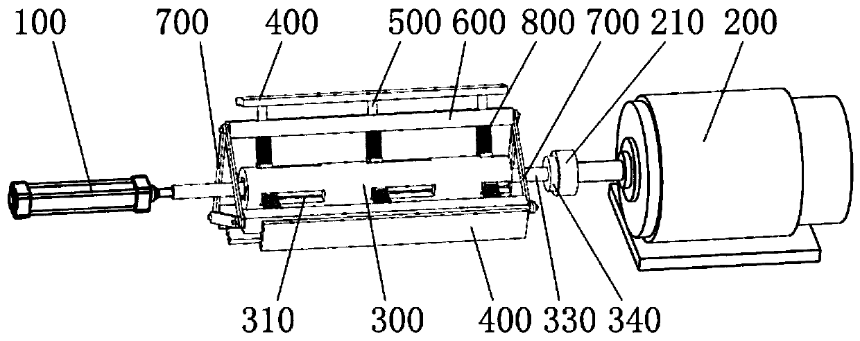
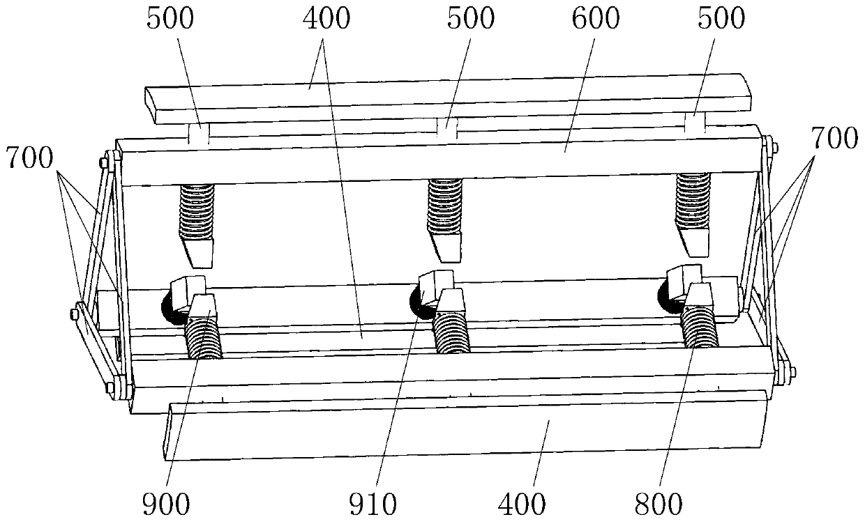
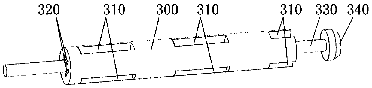
[0035] Please also refer to Figure 1 to Figure 5 , the embodiment of the present invention provides a feeding mechanism, which includes a cylinder 100, a motor 200, an adjustment shaft 300, a fixing seat and a support rod 400; wherein, one end of the adjustment shaft 300 is fixedly connected with the cylinder rod of the cylinder 100, and the adjustment shaft The other end of 300 is matched with the drive shaft of motor 200; the adjustment shaft 300 is provided with a chute 310, and the side of the chute 310 close to the cylinder 100 is ...


PUM


Abstract

The invention discloses a feeding mechanism. The feeding mechanism comprises an air cylinder, a motor, an adjusting shaft, a fixed seat and supporting rods; one end of the adjusting shaft is fixedly connected with an air cylinder rod of the air cylinder, and the other end of the adjusting shaft is fixedly connected with a driving shaft of the motor; sliding grooves are formed in the adjusting shaft; first inclined faces are arranged on the side faces, close to the air cylinder, of the sliding grooves, and an obtuse angle is formed between each first inclined face and the direction of the motor; the adjusting shaft is arranged in the fixed seat, and guide holes are formed in the fixed seat; and sliding rods are fixedly arranged on the supporting rods, the ends of the sliding rods penetratethrough the guide holes to be slidably connected with the sliding grooves, and second inclined faces matched with the first inclined faces are arranged at the ends of the sliding rods. According to the feeding mechanism, automatic adjustment of the coiled material supporting diameter is achieved, feeding and discharging operation of a coiled material is facilitated, and the problem that in the prior art, feeding and discharging are difficult due to deviation of a coiled material hole is solved.

Description

technical field [0001] The invention relates to the technical field of punching and feeding, in particular to a feeding mechanism. Background technique [0002] For punching, the material is generally changed from coil blanking to square material. In the prior art, the motor directly drives the rotating shaft to realize the rotation of the coil. However, this structure in the prior art has poor flexibility, and generally cannot realize automatic adjustment, especially when there is a deviation in the coil hole, it is difficult to load and unload. Contents of the invention [0003] The purpose of the present invention is to provide a feeding mechanism to realize the rotation of the feeding and at the same time realize the automatic switching of the inner diameter change of the coil. [0004] The invention provides a feeding mechanism, including: [0005] cylinder; [0006] motor; [0007] An adjustment shaft, one end of the adjustment shaft is fixedly connected with the...

Claims


Application Information

Patent Timeline
Patent Type & Authority Patents(China)
IPC IPC(8): B21C47/18B21C47/30
CPCB21C47/18B21C47/30
Inventor 何成周晶晶崔礼春杜长胜佘威何桂姣王双枝黄顶社
Owner ANHUI JIANGHUAI AUTOMOBILE GRP CORP LTD
Why Eureka
Try Eureka