

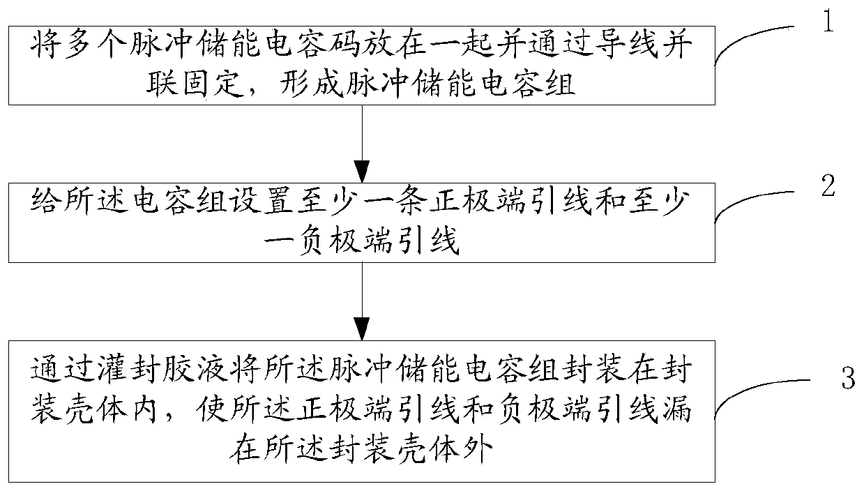
A kind of packaging method and packaging structure of pulse energy storage capacitor
A technology of energy storage capacitors and packaging methods, which is applied in the directions of packaging capacitor devices, capacitors, and capacitor manufacturing, etc., can solve the problems of difficult fixing, the inability of printed circuit boards to meet the requirements of satellite space miniaturization, and restricting the scope of application, and achieve simplification. The effect of fixed installation method, improving space utilization, and improving safety and reliability
- Summary
- Abstract
- Description
- Claims
- Application Information
AI Technical Summary
Problems solved by technology
Method used
Image

Examples
specific Embodiment
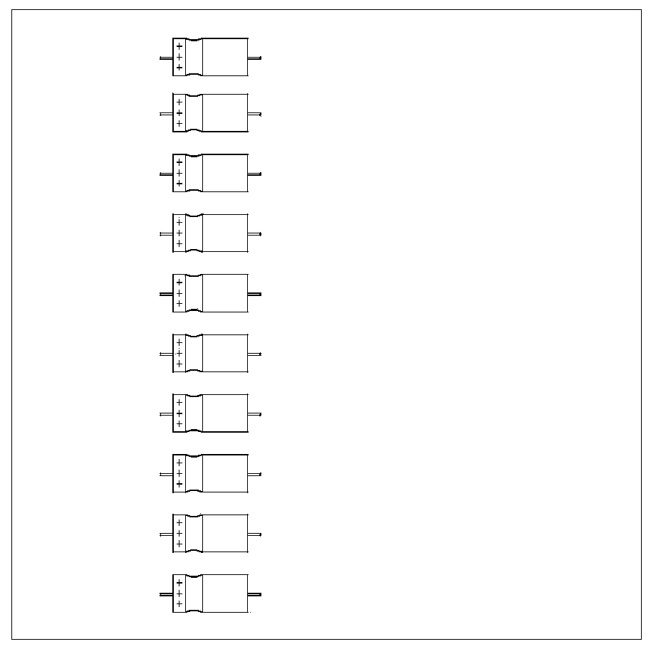
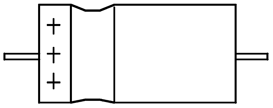
[0071] The tantalum capacitor in this embodiment is a CAK38-125V-82uF-K axial non-solid electrolyte all-tantalum capacitor.
[0072] Step 1: Take 16 tantalum capacitors 1, and trim the positive and negative pins of each tantalum capacitor so that the length of the trimmed pins is 3mm, and the solder joints on the positive pins cannot be damaged when trimming ;
[0073] Step 2: If Figure 5 with 6 As shown, according to the principle that the same polarity is on the same side, the trimmed 16 tantalum capacitors are stacked into a two-layer and two-column structure. In this structure, there are 8 tantalum capacitors in each layer and 8 tantalum capacitors in each column; The homopolar pins on the left side of the structure follow the Figure 5 The method shown is welded on a silver-plated copper wire with a diameter of 0.7mm. After welding, the silver-plated copper wire forms an inverted "mesh" structure. Figure 4 The method shown is welded on a silver-plated copper wire wi...
PUM
| Property | Measurement | Unit |
|---|---|---|
| diameter | aaaaa | aaaaa |
| size | aaaaa | aaaaa |
Abstract
Description
Claims
Application Information