
An automatic assembly riveting machine with usb interface

A USB interface, automatic assembly technology, applied in the direction of manufacturing tools, other manufacturing equipment/tools, etc., can solve the problems of inability to achieve continuous and uninterrupted riveting, time-consuming production, low efficiency, etc., to achieve good peeling effect, improve efficiency, Ensure the effect of peeling effect

Active Publication Date: 2019-09-10
安徽瑞尔特仪表科技有限公司
View PDF7 Cites 0 Cited by
  • Summary
  • Abstract
  • Description
  • Claims
  • Application Information

AI Technical Summary

Problems solved by technology

[0003] Most of the existing riveting of the USB interface is to first put the lower shell on the carrier of the riveting device, then place the interface main body and the upper shell on the lower shell, and then manually insert the rivets into the locking holes of the upper and lower shells After that, the riveting assembly of the interface is completed by pressing down the mechanical equipment. This method requires manual placement of the upper shell, lower shell, interface body and rivets, and the operation is cumbersome. After docking with the main body of the interface, a riveting machine is initially welded to form a whole, and then the whole is manually discharged, which relatively simplifies the operation steps and improves the working effect, but it still needs to be used for discharging the rivets, which consumes a lot of production man-hours , resulting in low riveting efficiency, unable to achieve continuous and uninterrupted riveting

Method used


Image

  • An automatic assembly riveting machine with usb interface
  • An automatic assembly riveting machine with usb interface
  • An automatic assembly riveting machine with usb interface

Examples


Embodiment Construction

[0046] In order to enable those skilled in the art to better understand the technical solution of the present invention, the present invention will be described in detail below in conjunction with the accompanying drawings. The description in this part is only exemplary and explanatory, and should not have any limiting effect on the protection scope of the present invention. .

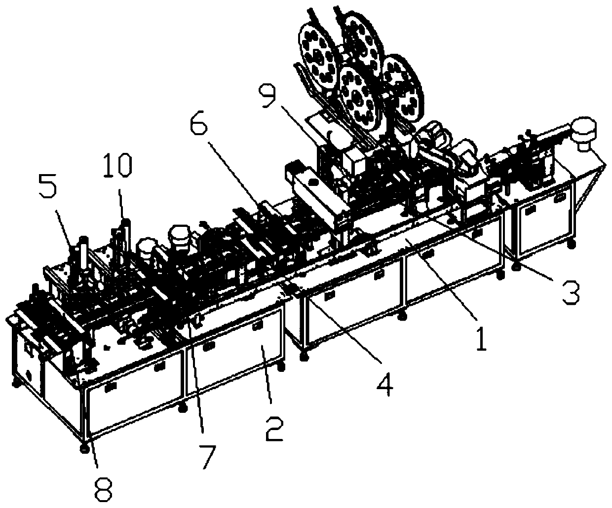
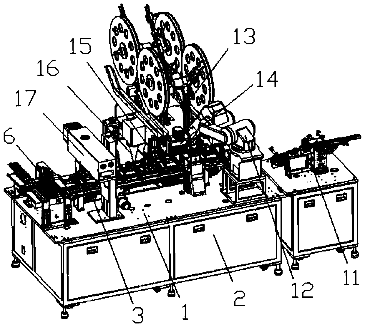
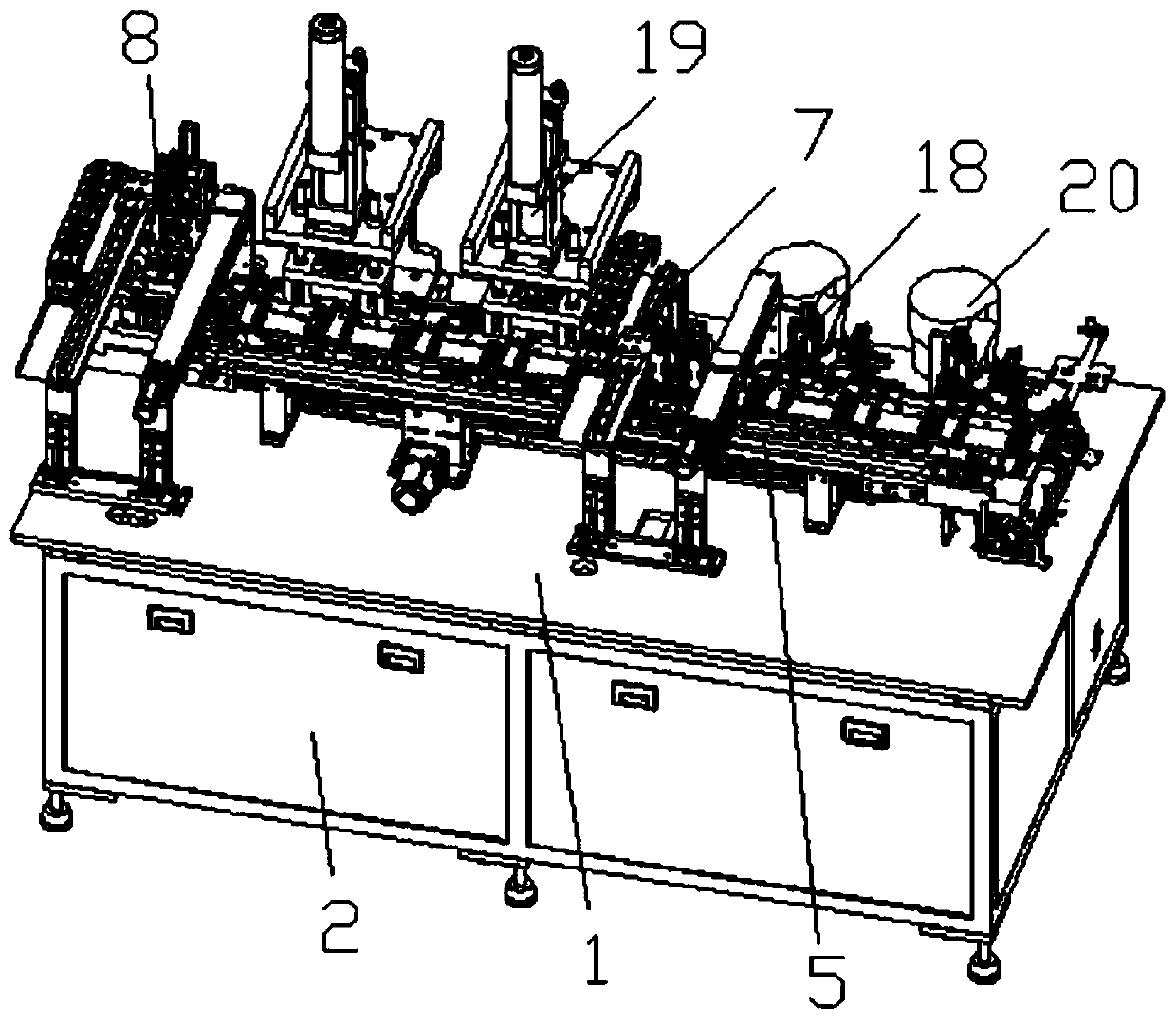
[0047] Such as Figure 1-Figure 18As shown, the specific structure of the present invention is: an automatic assembly riveting machine with a USB interface, which includes a frame 1 and a power distribution control box 2, and the frame 1 is provided with a shell docking device 9, a docking delivery device 4 and the riveting device 10, the riveting device 10 includes a riveting conveying device 5 arranged on the frame 1 and a second pick-and-place manipulator 7 which cooperates with the docking conveying device (4) and is sequentially arranged along the conveying direction of the riveting conveying devi...


PUM


Abstract

The invention relates to a USB interface automatic assembly riveting machine. A shell mounting and butting device, a butting and conveying device and a riveting device are arranged on a rack. The riveting device comprises a riveting conveying device, a second taking and placing manipulator, a rivet feeding device, a rivet pressing device and a third taking and placing manipulator. The butting and conveying device is matched with the shell mounting and butting device through a first taking and placing manipulator. The rivet feeding device comprises a rivet feeding seat. The rivet feeding seat is provided with a rivet conveying chute matched with a rivet vibration feeding disk. The tail end of the rivet conveying chute is provided with a rivet feeding butting port. A rivet pressing rod is arranged above the rivet feeding butting port in a matched mode, and the rivet feeding device is arranged below the rivet feeding butting port in a matched mode. The rivet pressing rod is arranged on a rivet pressing block. A rivet press-in rod matched with a product on a rivet pressing block is arranged in the position, over a conveying carrier, of the rivet pressing block. The USB interface automatic assembly riveting machine achieves automatic and continuous riveting through the rivet feeding device and the rivet pressing device, achieves accurate and continuous rivet feeding and improves the riveting efficiency.

Description

technical field [0001] The invention relates to the field of electronic product processing equipment, in particular to an automatic assembly riveting machine with a USB interface. Background technique [0002] The USB interface is a commonly used electronic connector. It mainly includes an interface body, an upper shell and a lower shell. Most of the parts will be provided with locking holes, which are locked by riveting rivets. [0003] Most of the existing riveting of the USB interface is to first put the lower shell on the carrier of the riveting device, then place the interface main body and the upper shell on the lower shell, and then manually insert the rivets into the locking holes of the upper and lower shells After that, the riveting assembly of the interface is completed by pressing down the mechanical equipment. This method requires manual placement of the upper shell, lower shell, interface body and rivets, and the operation is cumbersome. After docking with th...

Claims


Application Information

Patent Timeline
Patent Type & Authority Patents(China)
IPC IPC(8): B23P23/00B21J15/10
CPCB21J15/10B23P23/00
Inventor 邓君杨坤
Owner 安徽瑞尔特仪表科技有限公司
Learn More