Portable tennis wall
A portable and tennis technology, applied in the direction of sports accessories, etc., can solve the problems of falling off the wall, weak fixing strength, reducing the application effect, etc., to achieve the effect of prolonging the service life, strong protection and simple structure
- Summary
- Abstract
- Description
- Claims
- Application Information
AI Technical Summary
Problems solved by technology
Method used
Image

Examples
Embodiment 1
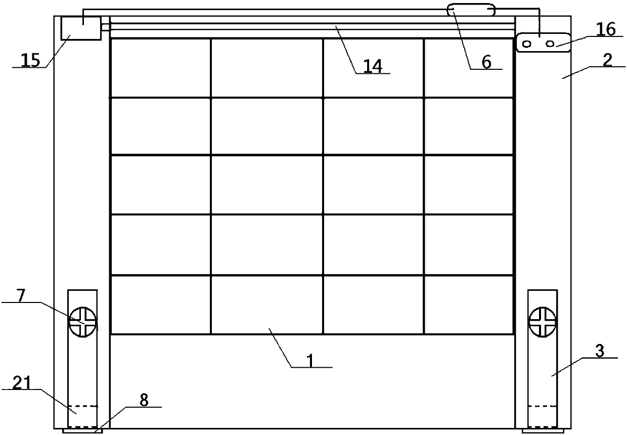
[0051] see figure 1 - Figure 8 , a portable tennis wall, comprising a wall body 1 and two supporting and fixing columns 2, the left and right sides of the wall body 1 are respectively connected with the inner side of a supporting and fixing column 2; the top of the wall body 1 is provided with The roller blind device 14, the drive shaft of the roller blind device 14 is connected with the output end of the drive motor 15, the power input end of the drive motor 15 is electrically connected with the power supply 16 through the temperature controller 6, and the drive motor 15, the temperature The controller 6 and the power supply 16 are all arranged on the top of the roller blind device 14;
[0052] The temperature controller 6 includes a metal casing 61, an input power cord 62, an output power cord 63, a wax block 65, and a conductive sheet 64. One end of the input power cord 62 is connected to the drive motor 15, and the other end of the input power cord 62 is passed through. ...
Embodiment 2
[0055] The basic content is the same as that of Example 1, except that:
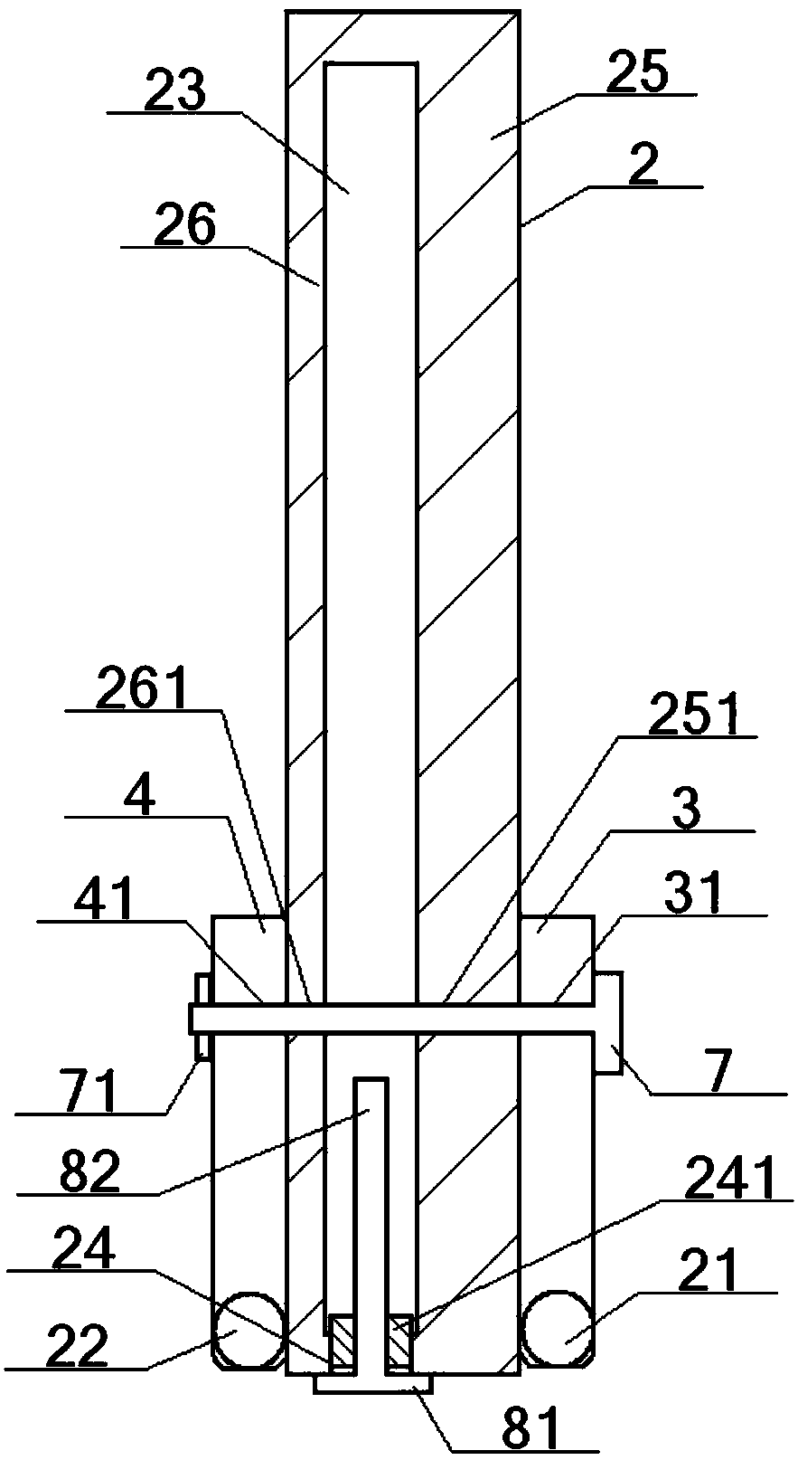
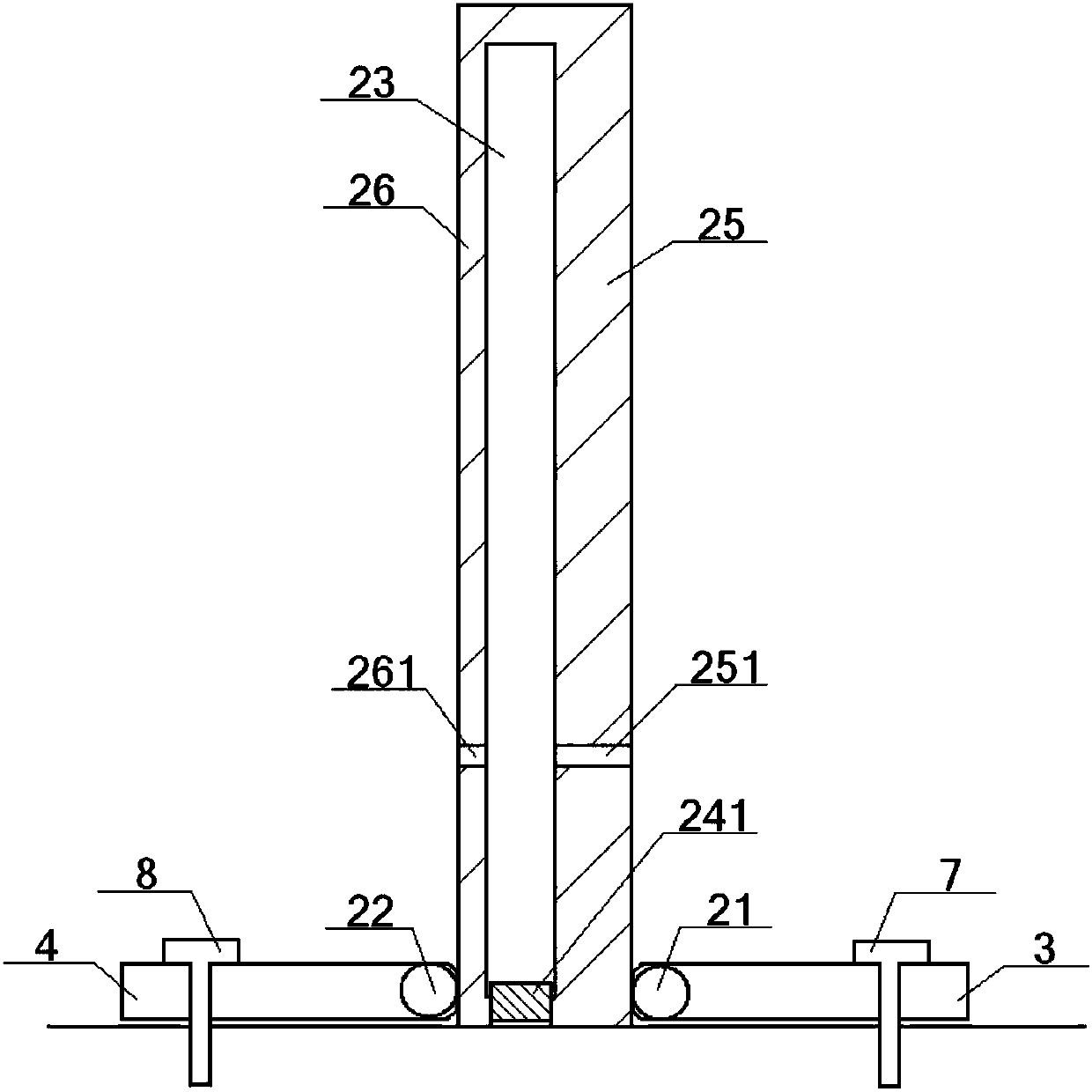
[0056] A hollow cavity 23 is opened inside the support and fixed column 2, and the bottom of the hollow cavity 23 communicates with the closed port 24 opened at the bottom of the support and fixed column 2. The closed port 24 is inlaid with a closed plug 241, and the interior of the closed plug 241 is The No. 2 fixing bolt 8 is threadedly connected, the bolt head 81 of the No. 2 fixing bolt 8 is flush with the bottom of the supporting fixing column 2, the bolt head 81 is connected with one end of the bolt column 82, and the other end of the bolt column 82 passes through in turn The closed port 24 and the closed plug 241 extend to the interior of the hollow cavity 23; the parts located on the front and rear sides of the hollow cavity 23 on the support and fixed column 2 are respectively the front cylinder 25 and the rear cylinder 26, and the front cylinder 25 is provided with a front wall hole 251, the re...
Embodiment 3
[0059] The basic content is the same as that of Example 2, except that:
[0060] The front rotating support shaft 3 is provided with the first two fixing holes 32 at the position between the former fixing hole 31 and the front rotating shaft 21 , and the rear rotating supporting shaft 4 is located at the rear fixing hole 41 and the rear rotating shaft 22 There are two rear fixing holes 42 in the part between; the front inclined column 5 and the rear inclined column 53 are placed in the hollow cavity 23; Bottom fixing holes 51, the top of the front inclined column 5 is provided with a front top fixing hole 52 corresponding to the front wall hole 251; the bottom of the rear inclined column 53 is provided with rear bottom fixing holes corresponding to the two rear fixing holes 42 54. A rear top fixing hole 55 corresponding to the rear wall hole 261 is formed on the top of the rear inclined column 53.
PUM
 Abstract
Description
Claims
Application Information
 - R&D
- Intellectual Property
- Life Sciences
- Materials
- Tech Scout
- Unparalleled Data Quality
- Higher Quality Content
- 60% Fewer Hallucinations
Browse by: Latest US Patents, China's latest patents, Technical Efficacy Thesaurus, Application Domain, Technology Topic, Popular Technical Reports.
© 2025 PatSnap. All rights reserved.Legal|Privacy policy|Modern Slavery Act Transparency Statement|Sitemap|About US| Contact US: help@patsnap.com