Continuous ignition type flame sprayer

A nozzle and flame technology, applied in the field of continuous ignition flame nozzle, can solve the problem of low combustion efficiency, achieve the effect of preventing clogging and convenient cleaning

Inactive Publication Date: 2018-03-06
朱毅
View PDF0 Cites 0 Cited by
  • Summary
  • Abstract
  • Description
  • Claims
  • Application Information

AI Technical Summary

Problems solved by technology

[0003] The technical problem to be solved by the present invention is: to overcome the technical problem of low combustion efficiency of the traditional combustion chamber structure in the prior art, and to provide a continuous ignition flame spray nozzle

Method used


Image

  • Continuous ignition type flame sprayer

Examples


Embodiment Construction

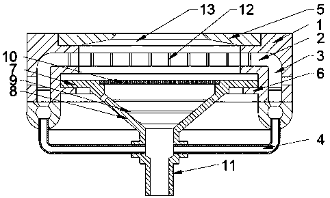
[0018] The present invention is described in further detail now in conjunction with accompanying drawing. These drawings are all simplified schematic diagrams, which only illustrate the basic structure of the present invention in a schematic manner, so they only show the configurations related to the present invention.

[0019] Such as figure 1 As shown, the present invention is a continuous ignition flame spray head, including a nozzle connection plate, an ignition plate and a gas nozzle, wherein the ignition plate includes an annular cavity arranged inside the nozzle connection plate, and the inner walls of the cavity Supported by a number of support columns; a nozzle is provided on the top of the nozzle connection plate, and a spray cover is provided at the end of the nozzle, and a flame injection cavity with a tapered structure is arranged inside the spray cover, and the aforementioned annular cavity is on the inner wall of the nozzle. opening; the side wall of the nozzle...


PUM


Abstract

The invention relates to a continuous ignition flame spray head, which comprises a nozzle connection plate, an ignition plate and a gas nozzle, wherein the ignition plate includes an annular cavity arranged inside the nozzle connection plate; a nozzle is arranged on the top of the nozzle connection plate, and the nozzle The end of the nozzle is provided with an injection cover plate, and a flame injection chamber with a tapered structure is arranged inside the injection cover plate. The aforementioned annular cavity is opened on the inner wall of the nozzle; the side wall of the nozzle connection plate is provided with an annular exhaust cavity; The annular array of the cavity is provided with a number of air intake pipes; the gas nozzle is coaxially arranged at the lower part of the nozzle connection plate corresponding to the ignition plate, the gas nozzle includes a nozzle body with a gradually expanding structure, and the flared end of the nozzle body is provided with a mesh structure The spoiler, the necking end of the nozzle body is connected with an air supply joint, the bottom of the air supply joint is connected with the air supply pipe, and the aforementioned annular array of air intake pipes is connected with the side wall of the air supply joint.

Description

technical field [0001] The invention relates to a continuous igniting flame spray head, which belongs to the field of gas equipment. Background technique [0002] The flame nozzle in the gas cooker is a device that ignites the gas and realizes continuous combustion. The traditional flame nozzle simply opens holes in several annular combustion chambers, and sprays the gas through the holes to achieve continuous combustion. This kind of structure is relatively simple, but the opening is easy to block, and for gas, the flow resistance is too large, the combustion efficiency is relatively low, and the impurities deposited in the combustion chamber will not be ignited and cannot be discharged, so it can be used for a long time Afterwards, serious preemptive total combustion will occur. Contents of the invention [0003] The technical problem to be solved by the present invention is: to overcome the technical problem of low combustion efficiency of the traditional combustion ch...

Claims


Application Information

Patent Timeline
Patent Type & Authority Applications(China)
IPC IPC(8): F23D14/04F23D14/58F23D14/70
CPCF23D14/04F23D14/58F23D14/70
Inventor 朱毅
Owner 朱毅
Why Eureka
Try Eureka