[0020] The embodiments of the present invention are described in detail below. Examples of the embodiments are shown in the accompanying drawings, wherein the same or similar reference numerals indicate the same or similar elements or elements with the same or similar functions. The embodiments described below with reference to the accompanying drawings are exemplary, and are intended to explain the present invention, but should not be construed as limiting the present invention.
[0021] In the following description, in order to clearly demonstrate the structure and working mode of the present invention, many directional words will be used for description, but the words "upper", "lower", "left", "right", "front", "rear" "," "in", "out", "up", "down", "left", "right", "forward", "backward", "inward", "outward" and other words It should be understood as a convenient term, not a restrictive term.
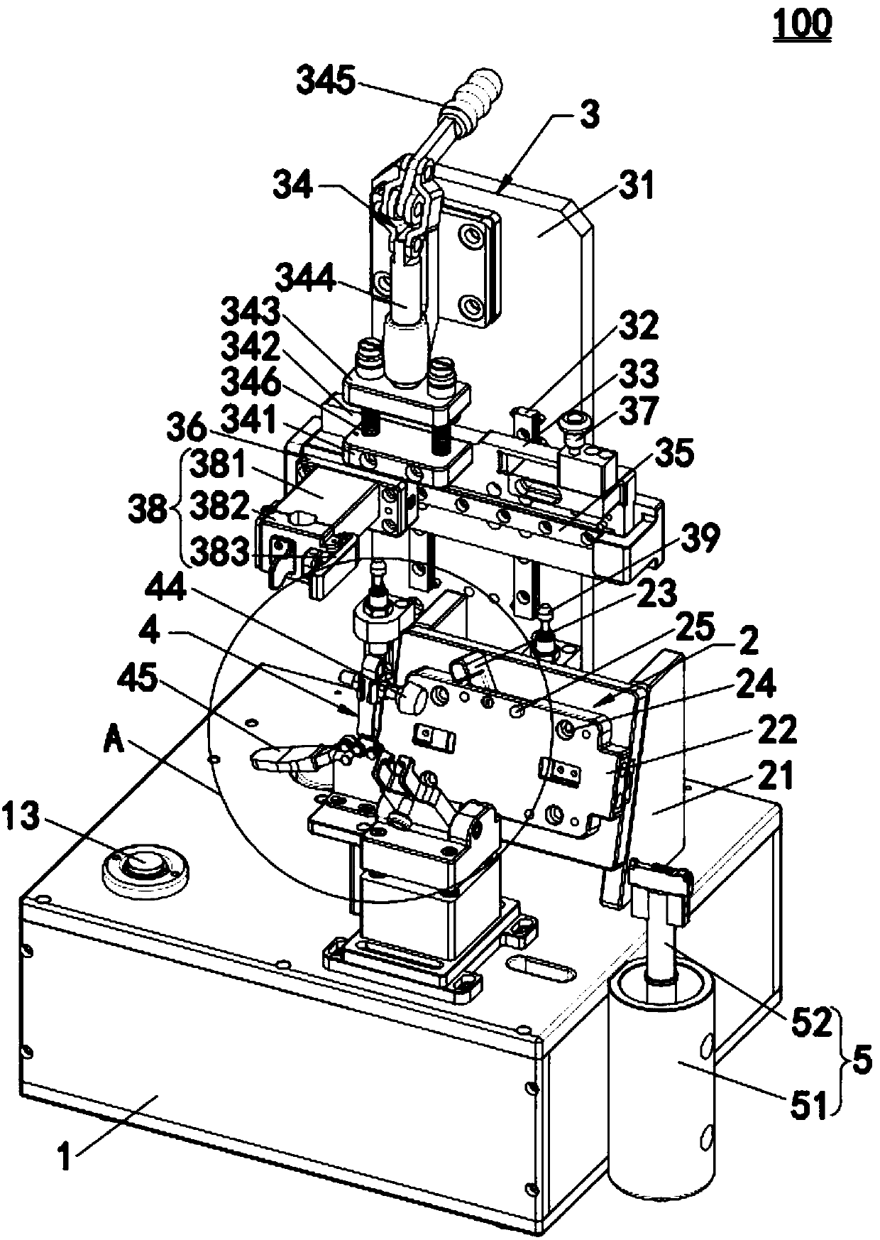
[0022] Such as figure 1 As shown, the present invention provides a smart watch speaker installation device 100, which includes a base 1, a positioning mechanism 2 arranged on the base 1, an assembly mechanism 3 arranged on one side of the positioning mechanism 2, and an assembly mechanism 3 arranged on the positioning mechanism 2. The turning and pressing mechanism 4 on the other side of the mechanism 2 and the pen suction unit 5 arranged on one side of the base 1. The positioning mechanism 2 positions the watch dial on which the speaker module is to be installed, the pen suction unit 5 sucks the speaker module to be installed, the assembly mechanism 3 clamps the pen suction unit 5, and the pen suction unit 5 The speaker module on the upper side is installed on the inside of the watch dial, and then the flip-down pressing mechanism 4 presses and fixes the speaker module, and the assembly mechanism 3 removes the pen suction unit 5, which realizes the automation of the speaker module Installation is convenient and efficient.
[0023] Such as figure 1 As shown, the positioning mechanism 2 includes a first mounting plate 21, a positioning carrier plate 22 provided on the first mounting plate 21, and a gland 23 hinged to one side of the positioning carrier plate 22; A number of positioning holes 24, positioning pins 25 and magnetic elements 26 are provided on the carrier board 22. The several positioning holes 24 and positioning pins 25 of the positioning carrier 22 play a role in positioning the product. After positioning, it is convenient to install the speaker module.
[0024] Such as figure 1 As shown, the assembly mechanism 3 includes a vertical plate 31 connected to the base 1, a first sliding rail 32 vertically arranged on the vertical plate 31, and a lifting plate slidably engaged with the first sliding rail 32 33. A driving unit 34 that drives the lifting plate 33 to slide along the first slide rail 32, a second slide rail 35 horizontally arranged on the lifting plate 33, and a second slide rail 35 slidably engaged with the second slide rail 35 A mounting block 36, a handle unit 37 that drives the first mounting block 36 to move along the second slide rail 35, and a clamping unit 38 mounted on the first mounting block 36. The driving unit 34 drives the lifting plate 33 and the second slide rail 35 to slide along the first slide rail 32 to achieve rising and falling, and the handle unit 37 is used to drive the first mounting block 36 along the The second slide rail 35 moves closer to or away from the positioning mechanism 2, the clamping unit 38 is used to clamp the pen suction unit 5 for installation of the speaker module, and the assembly mechanism 3 has a simple structure , Easy to operate.
[0025] Such as figure 1 and Figure 4 As shown, the driving unit 34 includes a pressure block 341, a guide block 343 connected to the pressure block 341 through a connecting column 342, a driving rod 344 connected to the guide block 343, and a lifting device that drives the driving rod 344 to lift. For the handle 345, a buffer spring 346 is sleeved on the connecting column 342, and the pressure block 341 abuts the lifting plate 33. The lifting handle 345 drives the driving rod 344 to go up and down, the driving rod 344 drives the guide block 343 and the pressing block 341 to go up and down, and the pressing block 341 drives the lifting plate 33 to go up and down, that is, the lifting plate is realized When the 33 is raised and lowered, the speaker module on the pen suction unit 5 can be press-fitted to the inside of the watch dial. The drive unit 34 has a simple and reliable structure, and is convenient and labor-saving to drive.
[0026] Such as figure 1 As shown, the clamping unit 38 includes a fixed plate 381 connected to the first mounting block 36, a movable plate 382 hinged to the fixed 381 plate, and is arranged on the movable plate 382 for fixing the A hook 383 clamped between the board 381 and the movable board 382. Between the fixed plate 381 and the movable plate 382 is formed a fixed groove that cooperates with the pen suction unit 5, and the hook 383 is used to fix the movable plate 382 and the fixed plate 381 to The pen suction unit 5 is fixed. Specifically, the hook 383 may be a clamping type. The hook 383 can be realized by pressing the hook 383 and another pressing part that cooperates with the hook 383. The clamping, the operation is simple and convenient.
[0027] Such as figure 1 As shown, the two ends of the first sliding rail 32 are respectively provided with buffers 39. The buffer 39 acts as a buffer during the lifting and lowering of the lifting plate 33, and can prevent the lifting plate 33 from being damaged by sudden excessive force.
[0028] Such as figure 2 , Combined figure 1 As shown, the turning and pressing mechanism 4 includes a second mounting block 41, a fork 42 hinged to the second mounting block 41, a turning handle 43 provided on the fork 42, and a second mounting block. The pressing head 44 on the side 41 and the pressing handle 45 driving the pressing head 44 to press the fork 42. The turning handle 43 is used to turn the fork 42 over to hold the product, and the hold handle 45 facilitates turning the indenter 44 over to hold the fork 42 so that the product can be effectively positioned. When the speaker is installed after positioning, the product will not shift in position.
[0029] Such as image 3 , Combined figure 1 As shown, the pen suction unit 5 includes a pen suction holder 51 connected to the base 1 and a suction pen 52 arranged in the pen suction holder 51. The suction pen 52 includes a pen handle 53 and a pen handle 53. One end of the suction head 54 is provided with a limit flange 55 on the pen handle 53, and one end of the suction head 54 is provided with a limit stop 56 and a wire avoiding groove 57. When installing the suction pen 52 to the clamping unit 38, the limiting flange 55 restricts the suction pen 52 so that the clamping unit 38 can effectively position the suction pen 52, The suction pen 52 is prevented from moving in the vertical direction; when the speaker is sucked, the limit rib 56 plays a role of positioning, and the wire avoiding groove 57 avoids interference with the speaker and the product.
[0030] Such as figure 1 and Figure 4 As shown, the base 1 is provided with a power plug 11, a start switch 12, a suction switch 13, and an electrostatic button 14; the power plug 11 is used to connect to an external power source, and the start switch 12 is used to control the smart The start and stop of the watch speaker installation device 100, the suction switch 13 is used to control the suction of the suction pen 52 and cancel the suction, the electrostatic button 14 prevents the generation of static electricity, which improves the smart watch speaker installation device 100 safety performance.
[0031] In the smart watch speaker installation device 100 of the present invention, the product is placed on the positioning carrier 22, the positioning hole 24 and the positioning pin 25 position the product, the suction pen 52 sucks the speaker, and the assembly mechanism 3 The clamping unit 38 clamps the suction pen 52, then the flip-down pressing mechanism 4 presses and fixes the speaker module, and the assembling mechanism 3 removes the suction pen unit 5, which realizes the speaker module The automatic installation of the group is convenient and efficient.
[0032] The above is only the best embodiment of the present invention, and does not limit the present invention in any form. Any person skilled in the art can use the method content disclosed above without departing from the scope of the technical solution of the present invention. Many possible changes and modifications to the technical solution of the present invention fall within the protection scope of the claims.