
Stator winding end insulation frame, plastic-packaging stator assembly, and plastic-packaging motor

A stator winding and end insulation technology, applied to the shape/style/structure of the winding insulation, can solve the problems of unfavorable automatic production and assembly of motors, high installation costs, and inconvenient installation, and improve the degree of automated production and installation process. Convenience and the effect of avoiding material waste

Active Publication Date: 2015-08-12
GUANGDONG WELLING ELECTRIC MACHINE MFG
View PDF5 Cites 8 Cited by
  • Summary
  • Abstract
  • Description
  • Claims
  • Application Information

AI Technical Summary

Problems solved by technology

[0005] The purpose of the present invention is to overcome the deficiencies of the above-mentioned prior art, and provide a stator winding end insulation frame, a plastic-sealed stator assembly and a plastic-sealed motor, which solve the problems of high installation cost, inconvenient installation, and easy to be damaged during the installation process of the existing PG plate components. Crushing, technical problems that are not conducive to the realization of automatic production and assembly of motors

Method used


Image

  • Stator winding end insulation frame, plastic-packaging stator assembly, and plastic-packaging motor
  • Stator winding end insulation frame, plastic-packaging stator assembly, and plastic-packaging motor
  • Stator winding end insulation frame, plastic-packaging stator assembly, and plastic-packaging motor

Examples


Embodiment 1

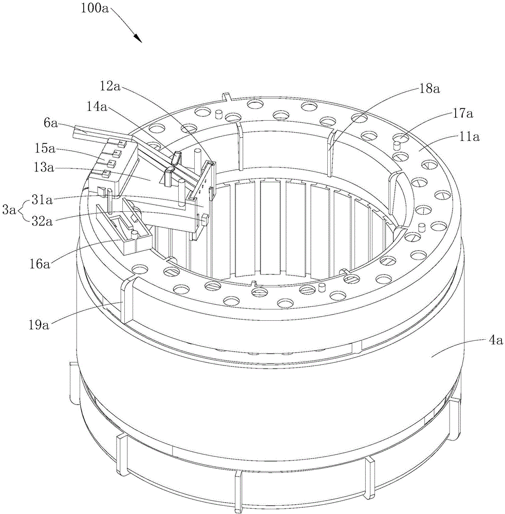
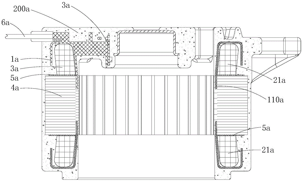
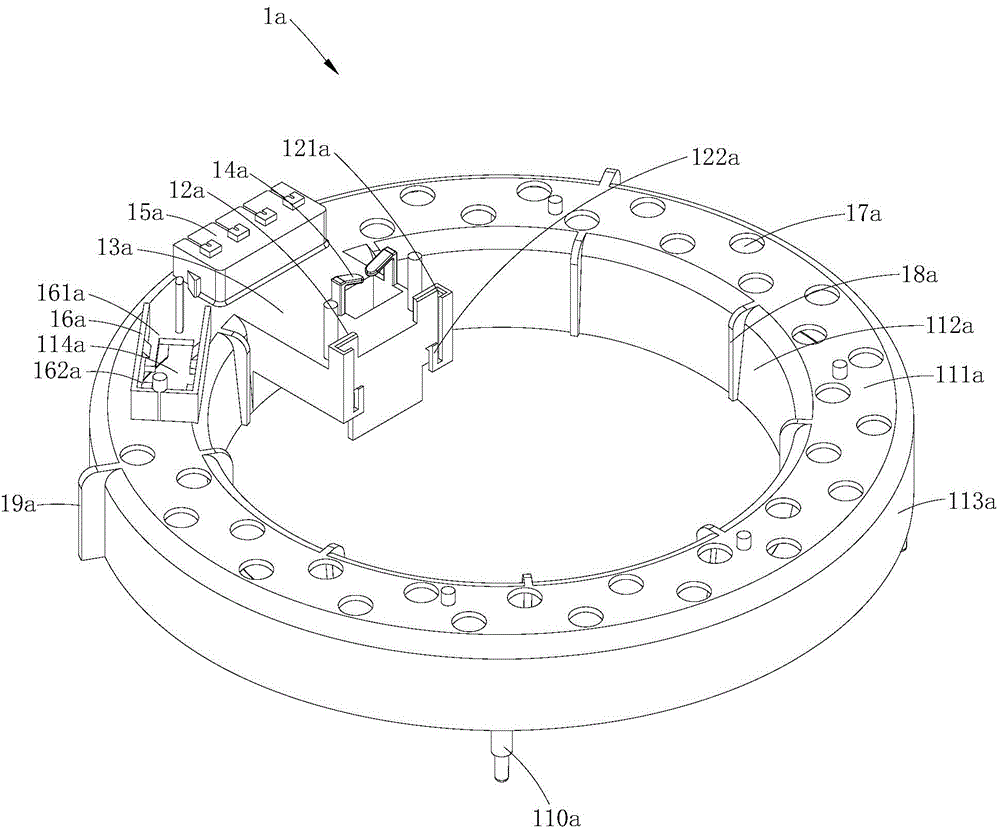
[0030] combined reference Figure 1~3 As shown, the stator winding end insulating frame 1a provided by Embodiment 1 of the present invention includes an insulating frame body 11a sleeved on the axial end 21a of the stator winding 2a along the motor axial direction. The PG plate member 3a is mounted on the PG plate mounting frame 12a, and the PG plate mounting frame 12a is provided with a slot 121a for receiving and positioning the PG plate component 3a. The PG board member 3a includes a circuit board 31a and a Hall element 32a provided on the circuit board 31a. In the stator winding end insulating frame 1a provided in this embodiment, the PG plate member 3a can be directly installed on the stator winding end insulating frame 1a by adding a PG plate mounting frame 12a on the insulating frame body 11a. In the specific installation process, the installation and positioning of the PG board member 3a can be realized by simply inserting the sliding card of the PG board member 3a in...

Embodiment 2

[0057] The main difference between the stator winding end insulation frame, the plastic-encapsulated stator assembly and the plastic-enclosed motor provided in this embodiment and the first embodiment lies in the different structural settings of the PG plate mounting frame. Specifically, in Embodiment 1, the insertion direction of the slot 121a is parallel to the axial direction of the motor; Image 6 with Figure 7 As shown, in this embodiment, the insertion direction of the slot 121b is perpendicular to the axial direction of the motor, and the PG plate component 3b is equivalent to being installed on the PG plate mounting frame 12b in a horizontal insertion manner. In this way, the PG plate component can also be realized The installation of 3b on the PG plate installation frame 12b is very convenient, and it is also conducive to the automatic installation of the PG plate component 3b.

[0058] Specifically, in this embodiment, the PG plate member 3b is inserted into the ca...


PUM


Abstract

The invention is suitable for the field of motors, and discloses a stator winding end insulation frame, a plastic-packaging stator assembly, and a plastic-packaging motor. The insulation frame comprises an insulation frame body which is disposed at an axial end part of a stator winding along the axial direction of a motor in a sleeve manner. The insulation frame body is provided with a PG plate installation frame which is used for the installation and positioning of a PG plate member, wherein the PG plate installation frame is provided with a clamping groove which is used for the storage and positioning of the PG plate member. According to the invention, the insulation frame body is additionally provided with the PG plate installation frame, thereby achieving the installation and positioning of the PG plate member only if the PG plate member is slidingly clamped and inserted in the clamping groove of the PG plate installation frame during installation. The installation is very convenient, thereby facilitating the implementation of the automatic installation of the PG plate installation frame. Moreover, the PG plate member cannot be damaged by pressing in an installation process, thereby guaranteeing the reliability of motor performances. Meanwhile, the reduction design of the PG plate member is also facilitated, thereby avoiding the material waste, and reducing the cost of a motor.

Description

technical field [0001] The invention belongs to the field of motors, and in particular relates to a stator winding end insulating frame, a plastic-sealed stator assembly with the stator winding end insulation frame and a plastic-sealed motor with the plastic-sealed stator assembly. Background technique [0002] The PG plate component is a part used in the PG motor to sense and detect the motor speed. In the prior art, the installation method of the PG plate component is generally as follows: the PG plate component is placed on the plastic-encapsulated stator assembly, and then the PG plate component is pressed and fixed by the motor end cover. This installation method has the following disadvantages in specific applications: [0003] 1) In order to ensure the reliability of the installation and positioning of the PG plate components, the circuit boards of the PG plate components are generally designed as semicircular plates or full circular plates around the rotating shaft,...

Claims


Application Information

Patent Timeline
Patent Type & Authority Applications(China)
IPC IPC(8): H02K3/34
CPCH02K3/38
Inventor 林春光范文陈可彬
Owner GUANGDONG WELLING ELECTRIC MACHINE MFG
Learn More