
Wide range glitchless switchable clock divider with modified 2/3 divider stages

A frequency divider and frequency divider chain technology, applied in the direction of pulse counter, automatic power control, counting chain pulse counter, etc., can solve the problems of increasing the frequency divider range and shortening the frequency divider chain.

Active Publication Date: 2018-03-06
SKYWORKS SOLUTIONS INC
View PDF6 Cites 0 Cited by
  • Summary
  • Abstract
  • Description
  • Claims
  • Application Information

AI Technical Summary

Problems solved by technology

One way to increase the range of the divider is to force the downstream stage to output a valid mod_out signal, thus shortening the divider chain

Method used


Image

  • Wide range glitchless switchable clock divider with modified 2/3 divider stages
  • Wide range glitchless switchable clock divider with modified 2/3 divider stages
  • Wide range glitchless switchable clock divider with modified 2/3 divider stages

Examples


Embodiment Construction

[0030] The above technique described by Vaucher et al. is used to avoid the 2 n to (2 n+1 -1) The crossover range limitation does not completely shut down the downstream stage. This means that downstream stages will still consume current and cause spurs on the output clock. Since the divider's supply voltage has a series resistance (unlike an ideal supply), drawing current through this resistor will cause modulation of the supply, resulting in spurious noise on the output clock. Nor does it provide a solution for switching the division ratio without failure. Using a divide-by-one approach draws extra current and adds extra delay, which limits the ability to change the divider ratio without glitches at high input frequencies.

[0031] Embodiments described herein shut down downstream stages to prevent spurious noise and provide the necessary circuitry to switch between any two valid division ratios without glitches. The advantage of the modified divider stage describe...


PUM


Abstract

A divider includes 2 / 3 divider stages that may be turned off without toggling to extend the divide range of the divider while also reducing the impact of spurs on the divider output, and preserving the timing margin to update the divide ratio glitchlessly. A 2 / 3 divider stage responds to an input enable signal being deasserted and a modulus input signal being asserted to remain in a disabled statein which the divider stage does not toggle by ensuring storage elements outputs in the divider stage remain constant. The divider further selects an update clock for the divide ratio of the divider utilizing an output from a most downstream stage that remains enabled.

Description

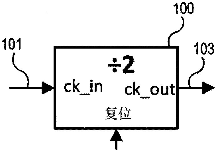
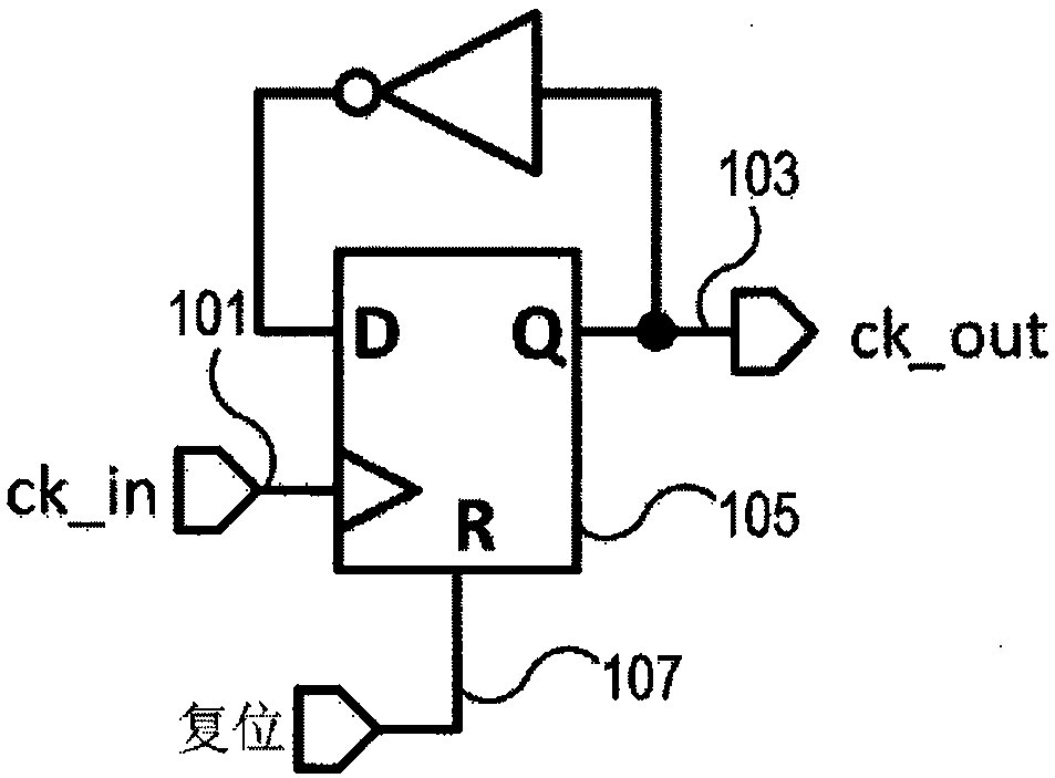
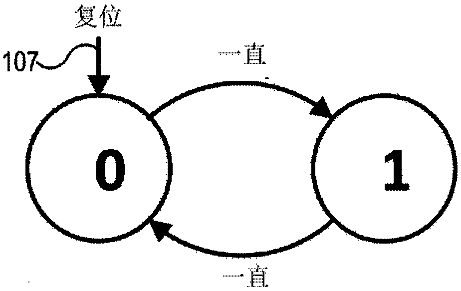
technical field [0001] The present invention relates to a frequency divider, and more particularly to a frequency divider using 2 / 3 frequency division stages. Background technique [0002] Frequency dividers are used in many different applications. For example, frequency divider applications include programmable frequency dividers, multimode frequency dividers in fractional-N phase-locked loops, and integer frequency dividers in interpolating frequency dividers. [0003] Dividers range from simple divide-by-2 circuits to more complex dividers such as multimode dividers. Figures 1A-1C A basic divide-by-two frequency divider 100 is shown. Figure 1A A high-level representation of a divide-by-two divider is shown. The input signal (ck_in) 101 is divided by two and provided as output signal (ck_out) 103 . Figure 1B An implementation of frequency divider 100 is shown where output 103 is inverted and fed back to the input of flip-flop 105 . Figure 1C A state machine is show...

Claims


Application Information

Patent Timeline
Patent Type & Authority Applications(China)
IPC IPC(8): H03K23/66H03L7/18
CPCH03K23/66H03L7/18H03K21/026H03K21/38
Inventor 布里安·G·德罗斯特
Owner SKYWORKS SOLUTIONS INC
Learn More