
A method for estimating instantaneous speed of rotating equipment

A technology of instantaneous speed and rotating equipment, applied in the field of signal processing, can solve the problems of cross-term interference, limited time-frequency resolution, poor time-frequency concentration, etc., and achieve the effect of simple implementation, overcoming the limitation of time-frequency resolution, and stable performance

Active Publication Date: 2021-04-02
SHANGHAI JIAO TONG UNIV
View PDF2 Cites 0 Cited by
  • Summary
  • Abstract
  • Description
  • Claims
  • Application Information

AI Technical Summary

Problems solved by technology

The disadvantages of these methods are: poor time-frequency concentration, cross-term interference, etc.
Although the parametric time-frequency analysis method improves the energy aggregation of the time-frequency distribution, its time-frequency resolution is still limited, and it is difficult to obtain high-precision instantaneous frequency estimates
[0004] So far, there is no use of parametric time-frequency method combined with envelope tracking filtering for instantaneous speed estimation of rotating equipment

Method used


Image

  • A method for estimating instantaneous speed of rotating equipment
  • A method for estimating instantaneous speed of rotating equipment
  • A method for estimating instantaneous speed of rotating equipment

Examples


Embodiment 1

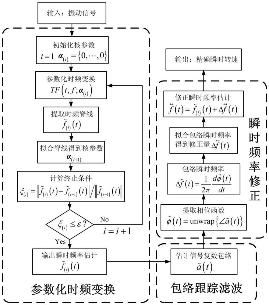
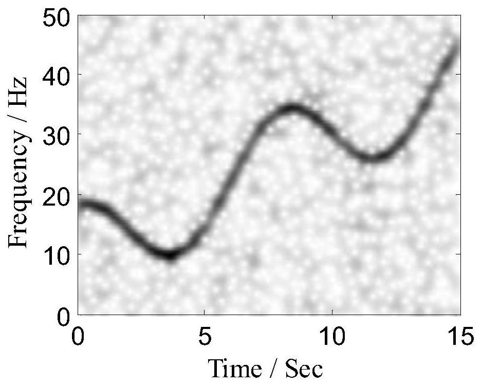
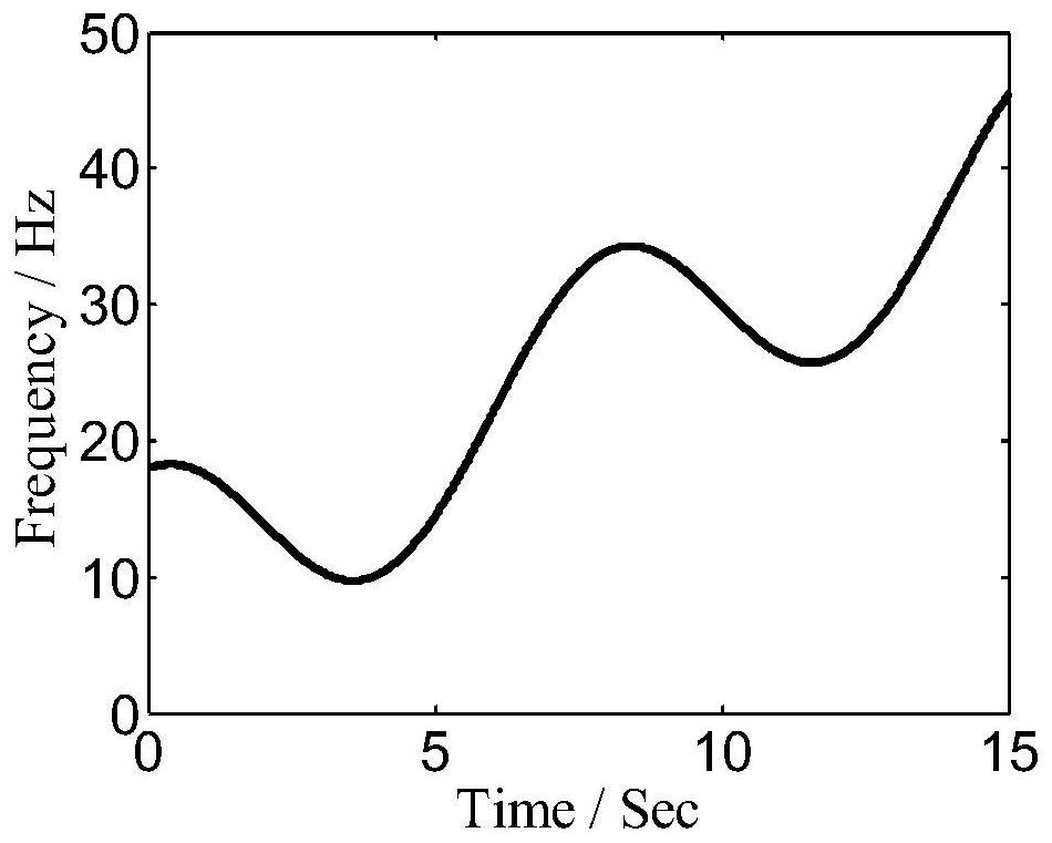
[0097] figure 2 It is the time-frequency representation of a simulated signal, the signal-to-noise ratio is 0dB, and the sampling frequency is 100Hz. Set the order M of the parameterized time-frequency transform Fourier kernel to 6, and the iterative convergence threshold ε to 1e-3. The parameterized time-frequency transformation is iterated 3 times to reach the convergence condition, and the relative errors of the instantaneous frequency estimation in each iteration are -43.9dB, -44.9dB, -45.0dB respectively. Use the envelope tracking filter to correct the instantaneous frequency estimation result, set the filter bandwidth to 1Hz (that is, the Fourier order K=15), and the regularization parameter α to 0.5, the corrected instantaneous frequency is as follows image 3 As shown, its relative error is -64.9dB. Figure 4 Relative error of instantaneous frequency estimation under different signal-to-noise ratio conditions for parameterized time-frequency transformation and the m...

Embodiment 2

[0099] The method provided by the invention will be used to estimate the instantaneous rotational speed of the actual equipment. Figure 5 It is a schematic diagram of a rotor test bench, in which the motor drives the load rotor to move after the speed is adjusted by the reducer, and the accelerometer collects the vibration signal at the bearing for analysis and processing. Figure 6 It is the time-frequency representation of the rotor vibration signal measured during the start-stop phase of the test bench, and the sampling frequency is 100 Hz. Set the order M of the parameterized time-frequency transform Fourier kernel to 30, and the iterative convergence threshold ε to 1e-3. The parametric time-frequency transformation is iterated a total of 3 times. Use the envelope tracking filter to correct the instantaneous frequency estimation result, set the filter bandwidth to 1Hz (that is, the Fourier order K=15), and the regularization parameter α to 0.5. The final estimated insta...


PUM


Abstract

The invention provides an instantaneous rotation speed estimation method for rotation equipment. According to the method, the instantaneous frequency of rotor vibration signals is precisely estimated,and thus rotation speed estimation of the equipment is achieved. The method comprises the steps that firstly, a parameterization time frequency analysis method is used for roughly estimating the instantaneous frequency of the vibration signals, then, a novel envelope tracking filter is used for precisely correcting an initial estimation result, and the finally obtained signal instantaneous frequency directly reflects the instantaneous rotation speed of the equipment; the envelope tracking filter uses a Fourier series model to depict the signal envelope, and a least square method is adopted for optimizing and solving an envelope parameter. According to the method, the instantaneous rotation speed estimation method which combines parameterization time frequency conversion with the envelopetracking filter is adopted, the defect can be overcome that the estimation precision is limited by the time frequency resolution ratio in the prior art, and the method has the advantages of high estimation precision and easy operation.

Description

technical field [0001] The invention relates to the field of signal processing, in particular to a method for estimating the instantaneous rotational speed of rotating equipment, in particular to a method for estimating the instantaneous rotational speed based on parameterized time-frequency transformation and envelope tracking filtering. Background technique [0002] In applications such as condition monitoring and fault diagnosis of large rotating equipment, it is usually necessary to accurately measure the instantaneous speed of the equipment. Key phase measurement is a commonly used method for instantaneous speed measurement of equipment. The key phase measurement method determines the position of the rotor within a rotation cycle by detecting the moment when the key phase pulse signal is generated. This method obtains the average rotational speed of the rotor, and when the rotational speed changes, the measurement error is large. At the same time, key phase measuremen...

Claims


Application Information

Patent Timeline
Patent Type & Authority Patents(China)
IPC IPC(8): G06F17/14G06F17/18H02P23/00H02P23/14
CPCG06F17/14G06F17/18H02P23/0077H02P23/14
Inventor 彭志科陈是扦
Owner SHANGHAI JIAO TONG UNIV
Learn More