Fully automatic die bonding machine

A crystal-bonding machine and fully automatic technology, which is applied in semiconductor/solid-state device manufacturing, semiconductor devices, electrical components, etc., can solve problems such as hindering the production process, low production efficiency, and unfavorable industrialized large-scale production, so as to reduce labor force, Improve the effect of intelligent operation and productivity

Active Publication Date: 2020-02-14
厦门市迅光电子有限公司
View PDF4 Cites 0 Cited by
  • Summary
  • Abstract
  • Description
  • Claims
  • Application Information

AI Technical Summary

Problems solved by technology

[0003] For the working process of LED crystal bonding, in the prior art, a plurality of splints are installed on the mold, and through manual arrangement, the LED legs are vertically fixed between the adjacent clips, so that the splints can clamp the LED bracket, Realize the function of arranging and fixing the LED legs individually on the template, and then fix them directly under the dispensing module for the die-bonding process. When receiving materials, disassemble the molds and unload them; this not only hinders the production process , while increasing the difficulty of processing operations, the production efficiency is low, which is not conducive to large-scale industrial production

Method used


Image

  • Fully automatic die bonding machine
  • Fully automatic die bonding machine
  • Fully automatic die bonding machine

Examples


Embodiment Construction

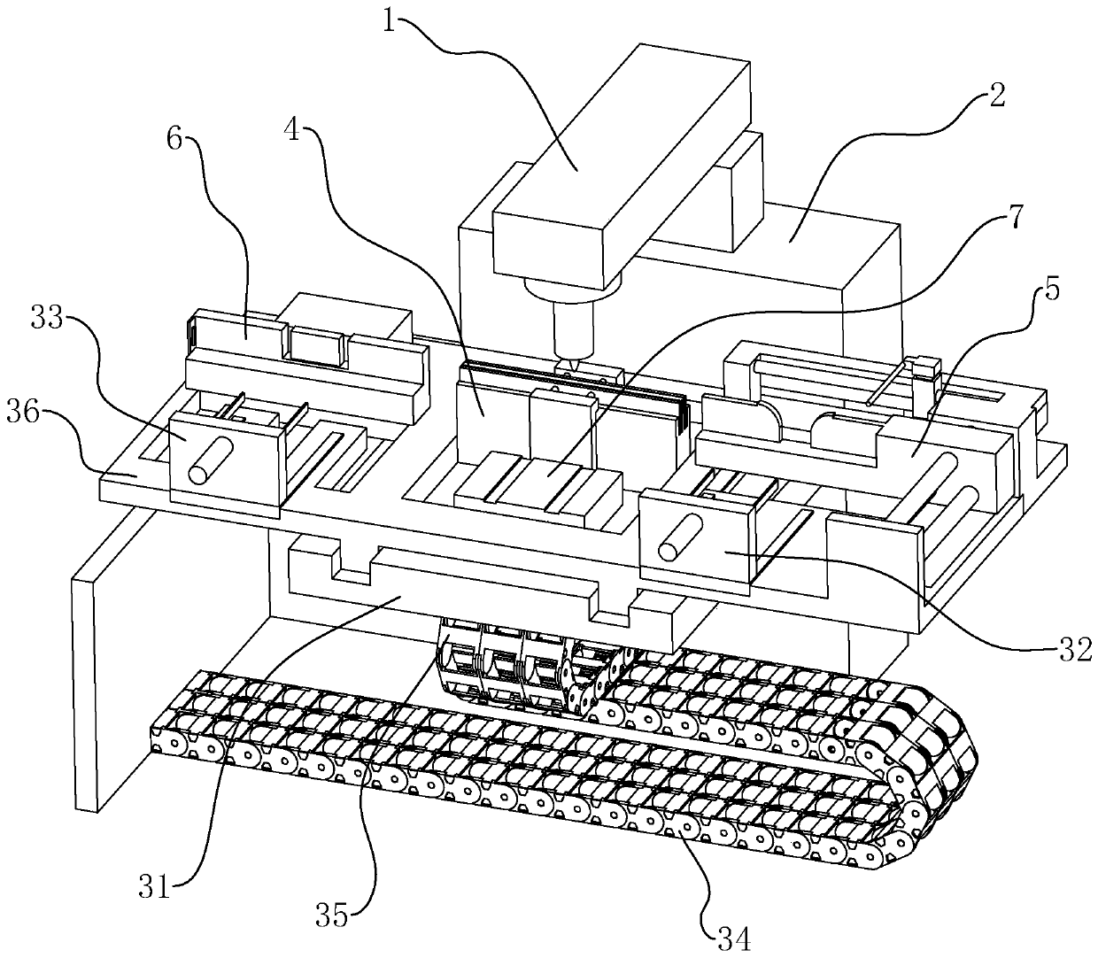
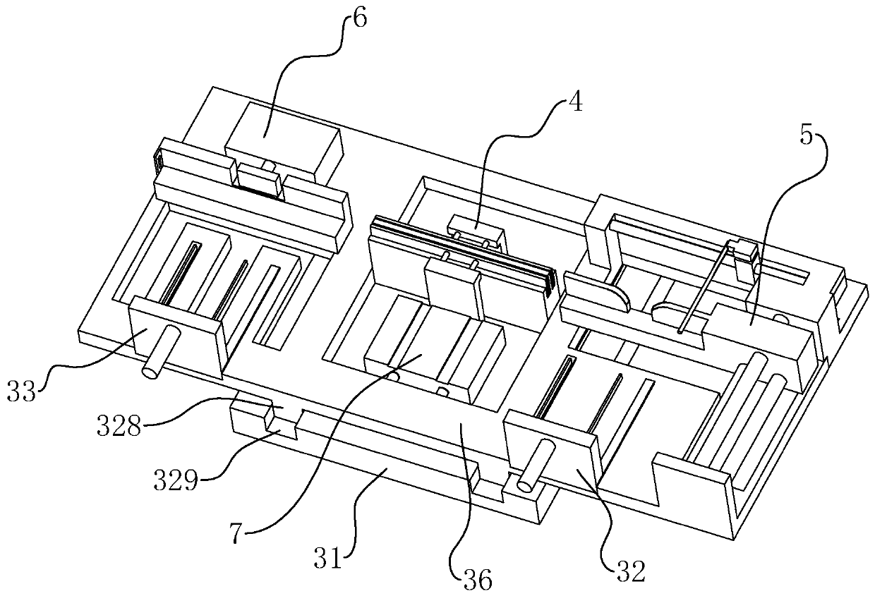
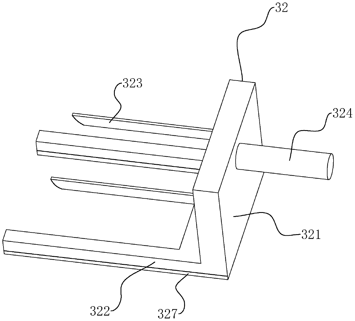
[0035] refer to Figure 1 to Figure 7 Further explain the fully automatic crystal bonder.

[0036] A fully automatic crystal bonder, such as figure 1 As shown, it includes three modules: an automatic feeding push and clamping device, a dispensing module 1 and an automatic receiving device; specifically includes a frame 2, a mounting frame 31 arranged on the frame 2, and a mounting frame 31 arranged on the mounting frame 31. The loading rack 32 for typesetting LED legs and the receiving rack 33 for receiving materials are arranged between the mounting frame 31 and the frame 2 for driving the mounting frame 31 to reciprocate horizontally on the frame 2 The moving transverse driving mechanism 34, the placing frame 36 arranged on the mounting frame 31, the longitudinal driving mechanism 35 arranged between the horizontal driving mechanism 34 and the mounting frame 31 for driving the placing frame 36 to reciprocate longitudinally on the mounting frame 31, The clamping mechanism 4 a...


PUM


Abstract

The invention discloses a full-automatic die bonde, comprising a frame, a dispensing module group disposed on the frame, a mounting rack disposed on the frame, a material feeding load plugging rack and a material recovering load plugging rack which are disposed on the mounting rack, a material clamping mechanism disposed below the dispensing module group, a material charging push mechanism which is disposed between the material clamping mechanism and the material feeding load plugging rack and used for conveying LEG legs to the material clamping mechanism, and a material recovering mechanism used for pushing the LED legs after die bond to the material recovering load plugging rack. The material feeding load plugging rack and the material recovering load plugging rack are respectively disposed at two sides of the material clamping mechanism. The invention is advantageous in that through the cycling of automatic material feeding, material distributing, and material recovering, the processing production integrating rapidness, high efficiency, and intelligence into one piece can be realized; the intelligent operation of die bond process of LED legs can be enhanced; labor force can be reduced, and productivity can be raised.

Description

technical field [0001] The invention relates to the technical field of LED production and manufacturing equipment, more specifically, it relates to a fully automatic crystal bonding machine. Background technique [0002] In the packaging process of semiconductor devices such as IC and LED, etc., die bonding is an extremely important link; LED die bonding machine is a model specially designed for LED product bonding, which is controlled by a computer and equipped with a CCD image sensor system. The CCD system scans to determine the correct path, then enters the set programming program, and easily presses the button to realize the entire workflow; the process of die bonding is: first, the feeding system transports the die bonding bracket in the storage device to the feeder. Then the die-bonding bracket moves along the feeding channel and stays at a certain position. At this time, the dispensing module on the frame automatically points the adhesive material, that is, sticks on ...

Claims


Application Information

Patent Timeline
Patent Type & Authority Patents(China)
IPC IPC(8): H01L21/67H01L33/48
CPCH01L21/67121H01L33/48H01L2933/0033
Inventor 高美法朱剑辉
Owner 厦门市迅光电子有限公司
Why Eureka
Try Eureka