Holographic display device and display method thereof
A technology of holographic display and imaging area, applied in the field of holographic display, can solve the problem of narrow viewing angle of holographic display device, and achieve the effect of improving viewing freedom and expanding the viewing angle range
- Summary
- Abstract
- Description
- Claims
- Application Information
AI Technical Summary
Problems solved by technology
Method used
Image
Examples
Embodiment 1
[0036] This embodiment provides a holographic display device, which includes:
[0037] an imaging unit, which is divided into multiple imaging areas, each imaging area is used to independently form a holographic image;
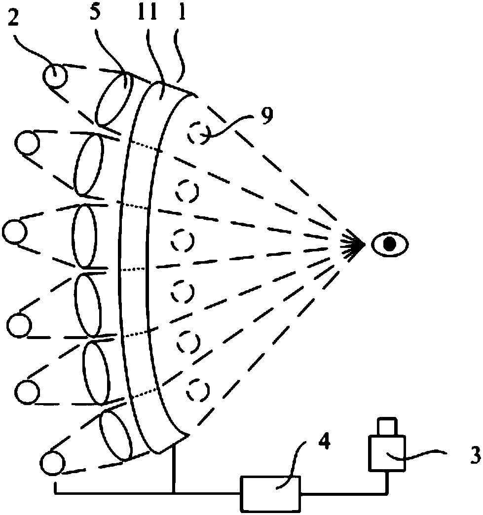
[0038] A light source unit, which includes a plurality of light source modules, each light source module is used to provide light for an imaging area, and the light emitted by each light source module points to the same viewing position after passing through the corresponding imaging area;
[0039] A human eye tracking unit for determining the direction of human eyes;
[0040] The control unit is used for controlling each light source unit and imaging area to perform holographic display according to the orientation of human eyes.
[0041] The imaging unit of the holographic display device of this embodiment is divided into a plurality of imaging areas that can independently form holographic images, and each imaging area is oriented differently, so that the li...
Embodiment 2
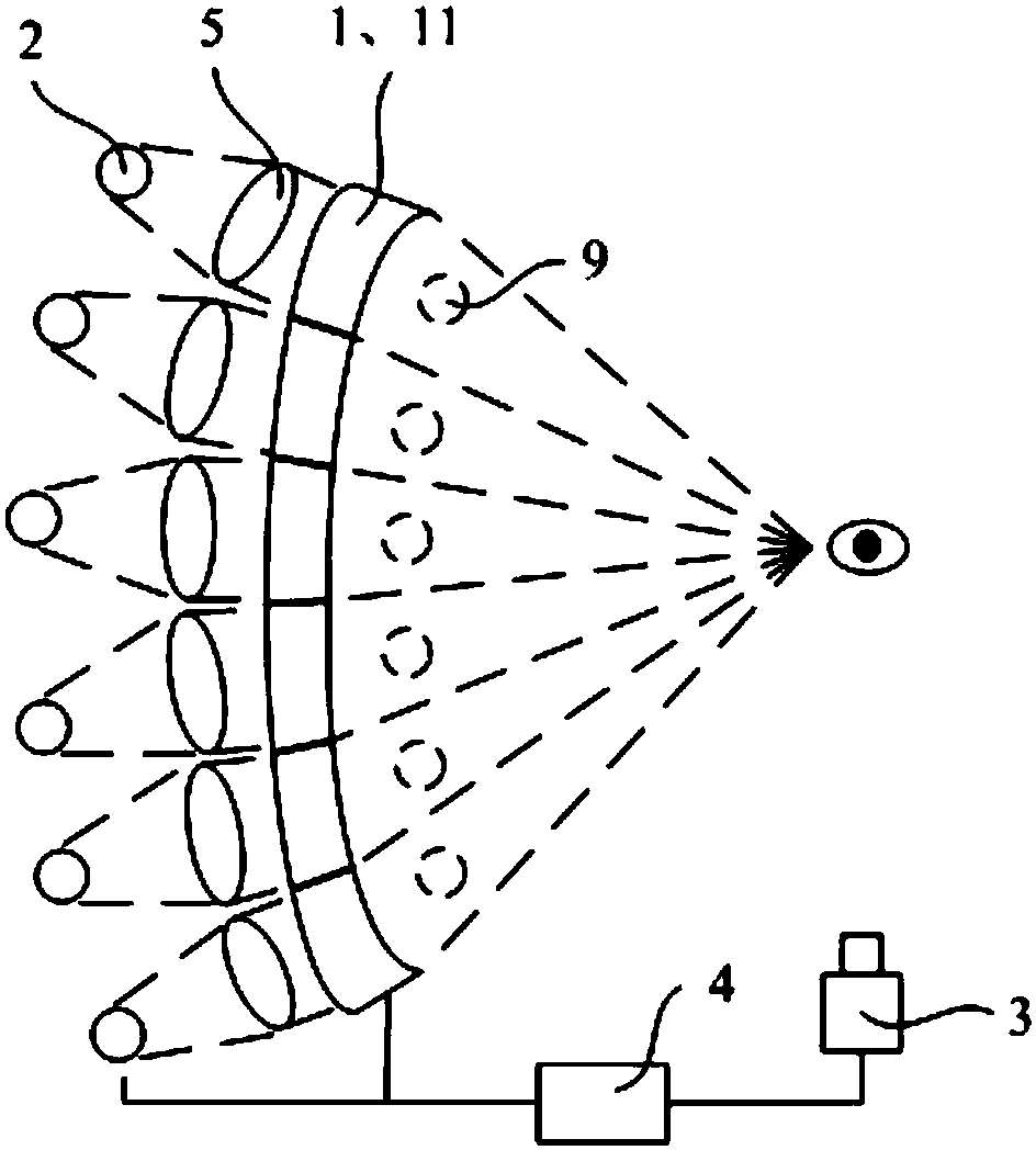
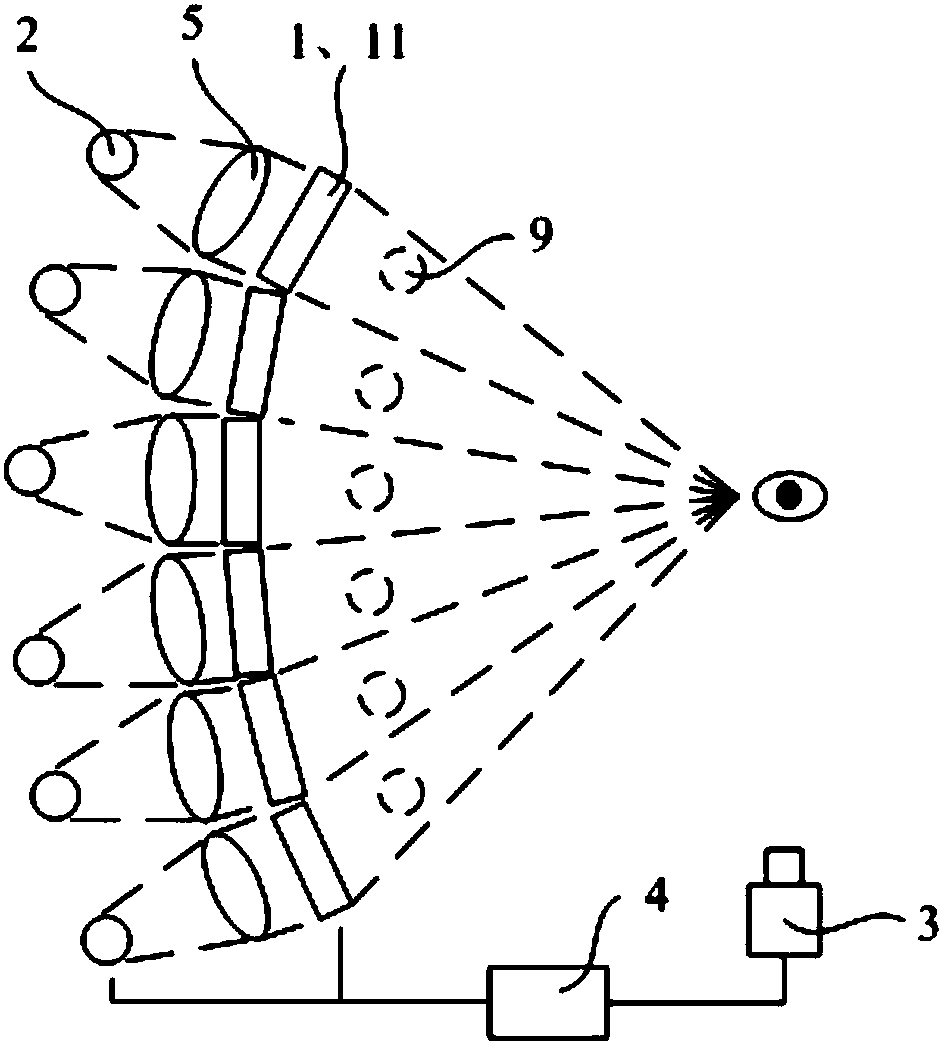
[0043] Such as Figure 1 to Figure 8 As shown, this embodiment provides a holographic display device, which has a structure similar to that of the holographic display device in Embodiment 1.
[0044] In this embodiment, the light emitting side of the imaging unit is a curved surface, more preferably a concave arc surface.
[0045] That is, if figure 1 , figure 2 As shown, the light-emitting side of the above imaging unit (that is, the side away from the light source unit) is preferably a smooth and continuous curved surface, and each imaging area 11 is a part of the curved surface, so each imaging area can be changed by adjusting the shape of the curved surface. The light output direction of zone 11. Wherein, in order to ensure that the light output of each imaging area 11 can point to the same viewing position, the above curved surface is preferably a concave curved surface (such as a part of a spherical surface). Of course, at this time, the viewing position should be lo...
Embodiment 3
[0066] This embodiment provides a display method of a holographic display device, and the holographic display device used is the above-mentioned display device; the display method specifically includes:
[0067] The human eye tracking unit determines the orientation of human eyes;
[0068] The control unit controls the light source unit and the imaging area corresponding to the current direction of human eyes to perform holographic display.
[0069] That is to say, when the above holographic display device is used for display, the human eye tracking unit should be continuously used to determine the direction of the human eye, and the light source unit and imaging area corresponding to the current human eye direction should be controlled at any time to perform holographic display, so that the user When the eye orientation changes within a certain range, the holographic image can be seen continuously, which expands the range of viewing angles and improves viewing freedom.
PUM
 Abstract
Description
Claims
Application Information
 - R&D
- Intellectual Property
- Life Sciences
- Materials
- Tech Scout
- Unparalleled Data Quality
- Higher Quality Content
- 60% Fewer Hallucinations
Browse by: Latest US Patents, China's latest patents, Technical Efficacy Thesaurus, Application Domain, Technology Topic, Popular Technical Reports.
© 2025 PatSnap. All rights reserved.Legal|Privacy policy|Modern Slavery Act Transparency Statement|Sitemap|About US| Contact US: help@patsnap.com


