Stator winding insulation structure adhered to two stator teeth

An insulating structure and stator winding technology, which is applied to windings, electrical components, electromechanical devices, etc., can solve the problems of reducing power density and winding amount, and achieve the effect of increasing winding amount and improving power density

Inactive Publication Date: 2018-03-13
TECO ELECTRIC AND MACHINERY
View PDF3 Cites 2 Cited by
  • Summary
  • Abstract
  • Description
  • Claims
  • Application Information

AI Technical Summary

Problems solved by technology

[0007] In view of the existing insulation structure, it generally causes the problem of reducing the amount of winding and reducing the power density

Method used


Image

  • Stator winding insulation structure adhered to two stator teeth
  • Stator winding insulation structure adhered to two stator teeth
  • Stator winding insulation structure adhered to two stator teeth

Examples


Embodiment Construction

[0060] Since the stator winding insulation structure attached to the two stator teeth provided by the present invention has too many combinations and implementations, it will not be repeated here, and only one preferred embodiment will be listed for specific description.

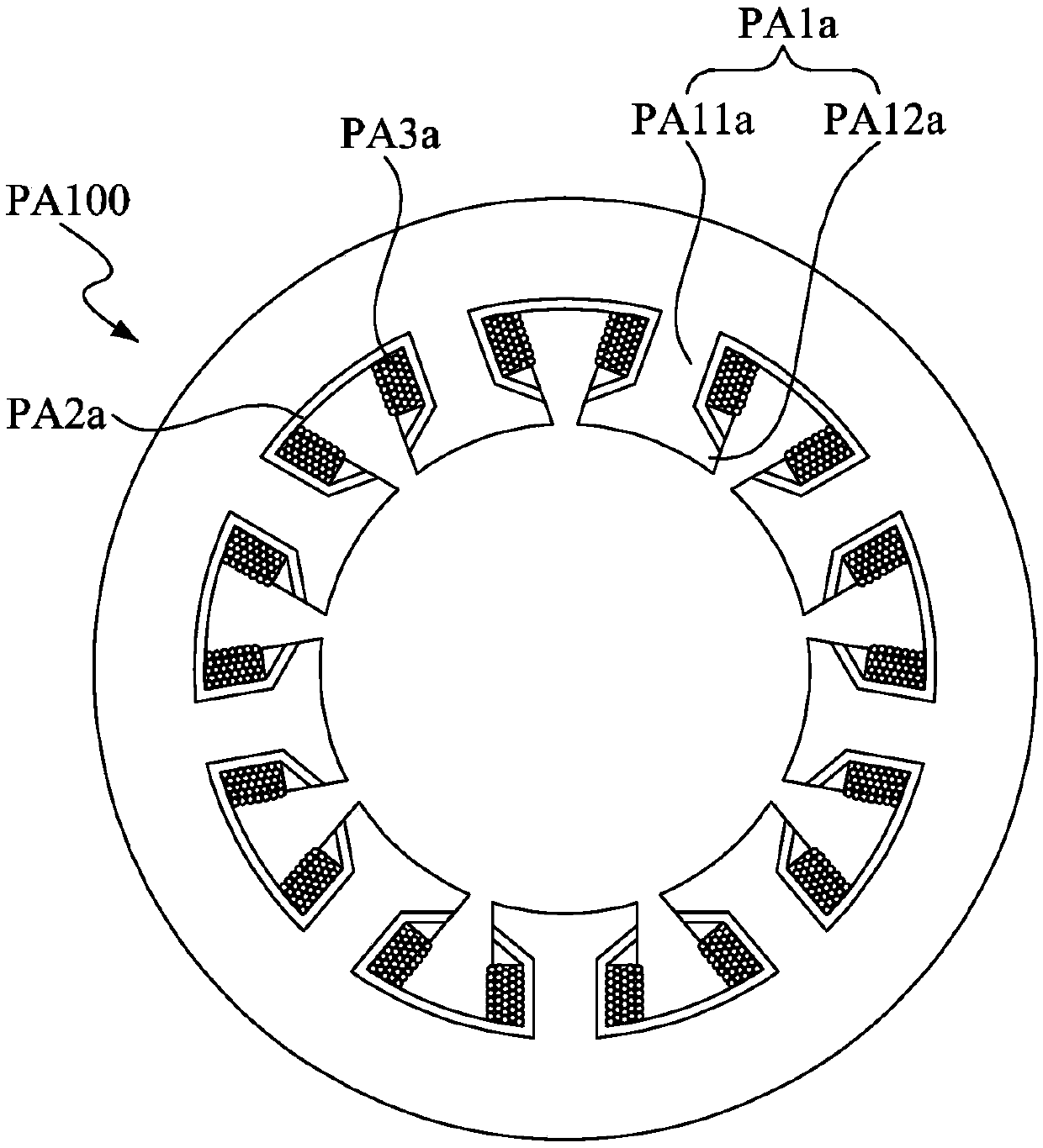
[0061] Please also refer to Figure 3 to Figure 6A , image 3 It is a schematic cross-sectional view showing that the stator winding insulation structure attached to the two stator teeth of the preferred embodiment of the present invention is arranged on the motor stator, Figure 4 A schematic cross-sectional view showing the structure of the tooth body. Figure 4A is displayed Figure 4 Partial enlarged view of the first ladder structure and the second ladder structure. Figure 5 It is a schematic cross-sectional view showing that the stator winding insulation structure attached to the two stator teeth of the preferred embodiment of the present invention is arranged on the motor stator and the winding is w...


PUM


Abstract

The invention relates to a stator winding insulation structure adhered to two stator teeth. The stator winding insulation structure is arranged on a motor stator which comprises a plurality of statorteeth. A winding space is formed between the stator teeth which are adjacent with each other. The stator winding insulation structure which adheres to the two stator teeth is arranged in the winding space. A first frame and a second frame extend from an insulation frame. At least one in a plurality of step structures of the frame extends from a first folding edge which is adjacent with the tooth body to a second folding edge that is far from the tooth body. The distance between the first folding edge and an axis is smaller than that between the second folding edge and the axis. At least one inthe plurality of step structures of the second frame extends from a third folding edge which is adjacent to the other stator tooth to a fourth folding edge that is far from the other stator tooth. The distance between the third folding edge and the axis is smaller than that between the fourth folding edge and the axis.

Description

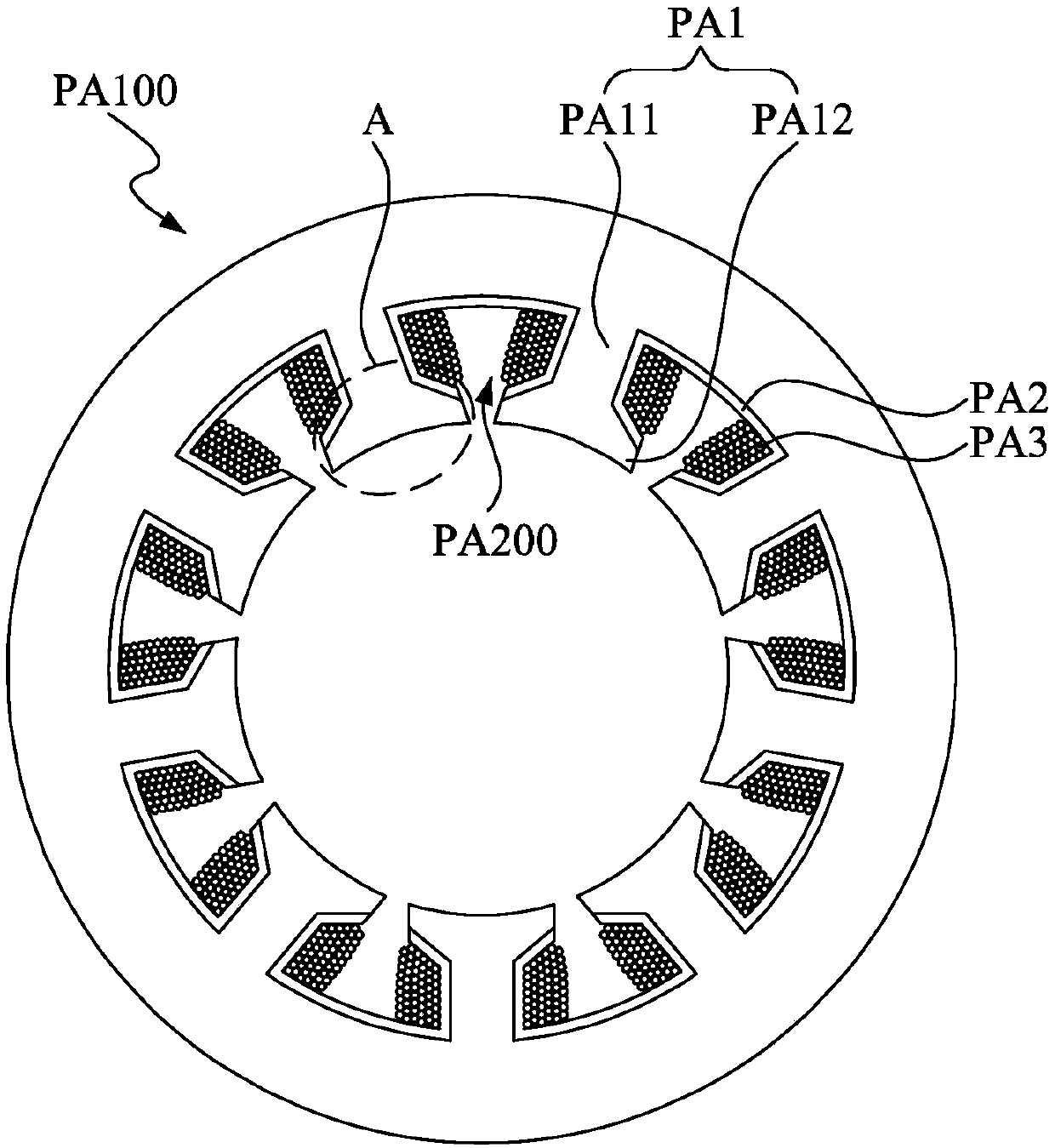
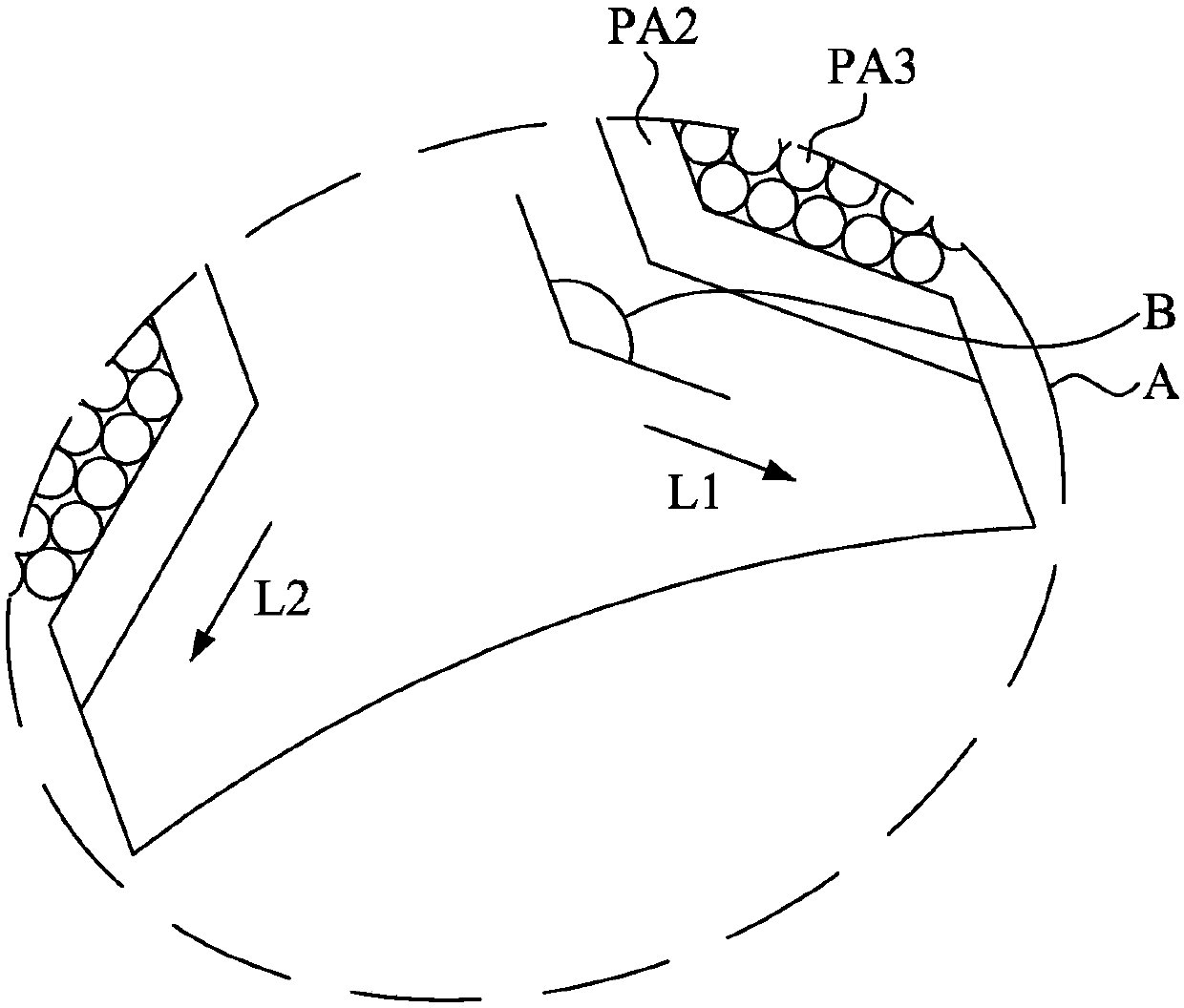
technical field [0001] The invention relates to a stator winding insulation structure attached to two stator teeth, in particular to a stator winding insulation structure arranged on a motor stator and including a stepped structure attached to two stator teeth. Background technique [0002] For a long time, induction motors such as motors have been the mainstream of rotating motors. They have been favored by people for a long time because of their practicality and durability. Motors are inseparable. A motor is a device that can effectively convert electrical energy into mechanical energy. In recent centuries, the motor industry has developed rapidly. Everything from generators in power plants to vibration motors in mobile phones are products of the motor industry. The principle that the motor can convert electrical energy into mechanical energy is based on Ampere's law in Maxwell's equations. The coil that introduces current will generate a corresponding magnetic field acco...

Claims


Application Information

Patent Timeline
Patent Type & Authority Applications(China)
IPC IPC(8): H02K3/52
CPCH02K3/522
Inventor 洪联馨黄庆智黄友伯
Owner TECO ELECTRIC AND MACHINERY
Why Eureka
Try Eureka