Transmission interval configuring method, device and user equipment

A technology of transmission interval and time interval, applied in the field of communication, can solve the problems of UE other equipment interference, affecting channel competition, etc., to achieve the effect of reducing the probability of interference and improving the success rate of competition

Active Publication Date: 2018-03-13
BAICELLS TECH CO LTD
View PDF4 Cites 9 Cited by
  • Summary
  • Abstract
  • Description
  • Claims
  • Application Information

AI Technical Summary

Problems solved by technology

[0010] The purpose of the present invention is to provide a method, device and user equipment for configuring transmission intervals, so as to solve the current problem that UE is often interfered by other devices due to the time interval between downlink reception and uplink transmission, which affects channel competition

Method used


Image

  • Transmission interval configuring method, device and user equipment
  • Transmission interval configuring method, device and user equipment
  • Transmission interval configuring method, device and user equipment

Examples


no. 1 example

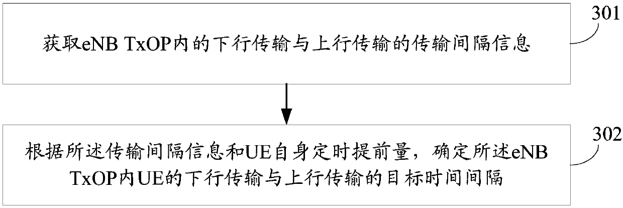
[0028] see image 3 As shown, the first embodiment of the present invention provides a method for configuring a transmission interval, which is applied to a user equipment, including steps 301-302, which are described in detail as follows.

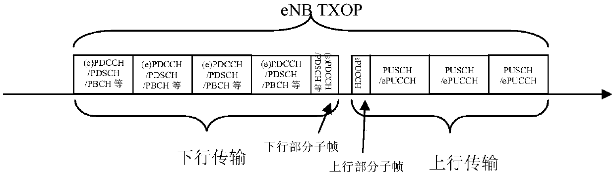
[0029] Step 301: Obtain transmission interval information between downlink transmission and uplink transmission in the eNB TxOP.

[0030] In the embodiment of the present invention, the transmission interval information includes at least the number of symbols of the downlink end subframe and the preset timing advance of the uplink transmission of the UE in the eNBTxOP, or at least includes the number of symbols of the downlink end subframe and the number of symbols of the eNBTxOP The preset time interval between downlink transmission and uplink transmission within .

[0031] Wherein, the number of symbols of the downlink end subframe may be indicated by the C-PDCCH on the downlink end subframe or the previous subframe of the downlink end ...

no. 2 example

[0038] see Figure 4 As shown, the second embodiment of the present invention provides a method for configuring a transmission interval, which is applied to a user equipment, including steps 401 to 403, which are described in detail as follows.

[0039] Step 401: Obtain the number of symbols of the downlink end subframe in the eNB TxOP and the preset timing advance of the UE's uplink transmission in the eNB TxOP.

[0040] In the embodiment of the present invention, the number of symbols of the downlink ending subframe and the preset timing advance are transmission interval information corresponding to downlink transmission and uplink transmission in the eNB TxOP. The preset timing advance can be used to enable the UE to adjust the sending time of the uplink transmission dynamically, periodically or fixedly. The preset timing advance may be notified in system information (generally corresponding to dynamic or periodic adjustment of uplink transmission sending time), or may be ...

no. 3 example

[0055] see Figure 5 As shown, the third embodiment of the present invention provides a method for configuring a transmission interval, which is applied to a user equipment, including steps 501 to 503, which are described in detail as follows.

[0056] Step 501: Obtain the number of symbols of the downlink end subframe in the eNB TxOP and the preset time interval between downlink transmission and uplink transmission in the eNB TxOP.

[0057] In the embodiment of the present invention, the number of symbols of the downlink ending subframe and the preset time interval are transmission interval information corresponding to downlink transmission and uplink transmission in the eNBTxOP. The preset time interval is a fixed time interval between downlink transmission and uplink transmission in the eNB TxOP, which may be notified in system information or pre-specified in a standard.

[0058] Step 502: Determine the initial sending time of uplink transmission of the UE in the eNBTxOP a...


PUM


Abstract

The invention provides a transmission interval configuring method, a device and user equipment (UE), wherein the transmission interval configuring method comprises the steps of acquiring transmissioninterval information in downlink transmission and uplink transmission in an eNB TxOP; and according to the transmission interval information and UE self timing advanced amount, and determining the target time interval in downlink transmission and downlink transmission of the UE in the eNB TxOP. The transmission interval configuring method, the device and the user equipment have advantages of realizing flexible supporting to different time intervals, improving equipment channel competition success rate and reducing interference probability between the equipment.

Description

technical field [0001] The present invention relates to the field of communication technologies, and in particular to a method, device and user equipment for configuring transmission intervals. Background technique [0002] A mobile communication system refers to a system in which operators provide communication services for user terminals (such as mobile phones) by deploying radio access network equipment (such as base stations) and core network equipment (such as Home Location Register, HLR). Among them, the mobile communication system has experienced the first generation, the second generation, the third generation and the fourth generation. The first-generation mobile communication system refers to the initial analog cellular phone standard, which is limited to voice calls, mainly using analog technology and Frequency Division Multiple Access (FDMA) access method; the second-generation mobile communication The system introduces digital technology, improves network capac...

Claims


Application Information

Patent Timeline
IPC IPC(8): H04W72/04H04W72/08
CPCH04W72/0446H04W72/54H04W72/20H04W56/00
Inventor 周明宇孙立新丁颖哲
Owner BAICELLS TECH CO LTD
Why Eureka
Try Eureka