Axial-flow type water control reducing valve

A pressure reducing valve, axial flow technology, applied in the field of axial flow water control pressure reducing valve, can solve the problems of high cost and short service life, and achieve the effect of low manufacturing cost, fewer failure points and good medium flow state

Pending Publication Date: 2018-03-16
ANHUI REDSTAR VALVE
View PDF9 Cites 1 Cited by
  • Summary
  • Abstract
  • Description
  • Claims
  • Application Information

AI Technical Summary

Problems solved by technology

Therefore, the service life of the current hydraulic control valve is short and the cost is high

Method used


Image

  • Axial-flow type water control reducing valve
  • Axial-flow type water control reducing valve
  • Axial-flow type water control reducing valve

Examples


Embodiment Construction

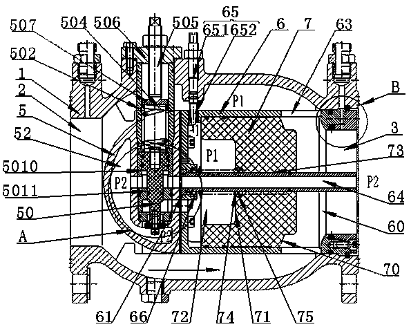
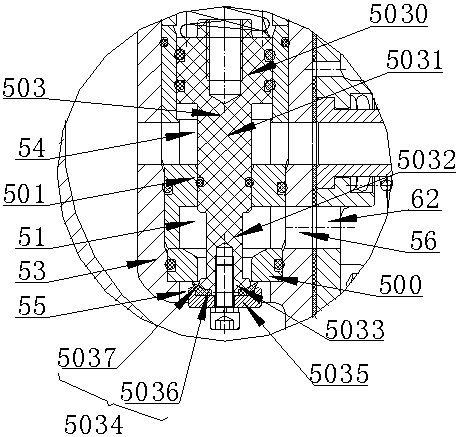
[0024] Combine below Figures 1 to 3 Describe the structure and content of the invention of the axial-flow water-controlled pressure reducing valve of the present invention.

[0025] An axial flow water control pressure reducing valve, comprising a valve body 1, a water inlet 2 and a water outlet 3 arranged at both ends of the valve body 1, a first valve seat 4 installed at the water outlet 3, arranged inside the valve body 1 and The pressure relief body 5 near the water inlet, the pressure relief valve 50 installed in the pressure relief body 5, the piston ring 6 installed on the pressure relief body 5, and the piston ring 6 installed in the piston ring 6 and sealed with the first valve seat 4 piston7.

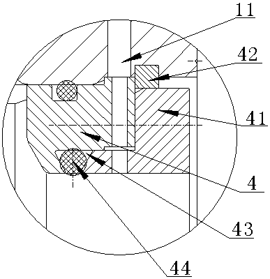
[0026] Pressure measuring holes 11 are provided on the valve body 1 at positions corresponding to the water inlet 2 and the water outlet 3 . A pressure measuring instrument is installed on the pressure measuring hole 11 .

[0027] The first valve seat 4 is sealingly instal...


PUM


Abstract

The invention provides an axial-flow type water control reducing valve. The axial-flow type water control reducing valve comprises a valve body, a water inlet and a water outlet which are formed in the two ends of the valve body, a first valve seat arranged at the water outlet, a pressure releasing body arranged in the valve body, a pressure releasing valve arranged in the pressure releasing body,a piston ring arranged on the pressure releasing body and a piston which is arranged in the piston ring and is in sealed fit with the first valve seat. The piston and the piston ring form a piston inner cavity. The piston ring is provided with a pressure guide pipe and a water inlet needle valve. The pressure releasing body is divided into an upper pressure releasing cavity and a lower pressure releasing cavity by the pressure releasing valve. The water inlet communicates with the piston inner cavity through the water inlet needle valve. The water outlet communicates with the lower pressure releasing cavity through the pressure guide pipe. When the pressure releasing valve is closed, the upper pressure releasing cavity communicates with the piston inner cavity. When the pressure releasingvalve is opened, the lower pressure releasing cavity communicates with the piston inner cavity. By means of the axial-flow type water control reducing valve, the control precision of opening and closing of the piston can be improved, and the gas etching and vibration borne by parts in the valve body can be weakened.

Description

technical field [0001] The invention relates to the field of valves, in particular to an axial-flow water-controlled pressure reducing valve. Background technique [0002] The hydraulic control valve is a valve that is driven by the pressure of the pipeline medium to open, close and adjust. The current hydraulic control valve consists of a main valve and an attached pilot valve. The pilot valve acts with the change of the liquid level and pressure of the medium. Since there are many types of pilot valves, they can be used alone or in combination, so that the main valve can obtain the function of individually and compoundly adjusting the water level, water pressure and flow. . [0003] Hydraulic control valves are divided into two types, diaphragm type and piston type. The working principle is the same. They are driven by the pressure difference between the upstream and downstream, controlled by the pilot valve, so that the hydraulic differential operation of the diaphragm ...

Claims


Application Information

Patent Timeline
Patent Type & Authority Applications(China)
IPC IPC(8): F16K17/30F16K47/02
CPCF16K17/30F16K47/023
Inventor 何锐罗凤英孙世林
Owner ANHUI REDSTAR VALVE
Why Eureka
Try Eureka