Stirring device

A stirring device and driving device technology, which is applied to mixers with rotating stirring devices, mixer accessories, transportation and packaging, etc., can solve the problems of poor stirring effect at the bottom of the tank, affecting the balance of the impeller, and large winding of the transmission shaft, etc., to achieve Eliminate the stirring dead zone, no stirring dead zone, and improve the stirring effect

Pending Publication Date: 2018-03-20
NANJING POLYTECHNIC INSITUTE
View PDF3 Cites 3 Cited by
  • Summary
  • Abstract
  • Description
  • Claims
  • Application Information

AI Technical Summary

Problems solved by technology

But the mixer of existing structure has the following problems: because the impeller has a certain distance from the bottom of the tank body, the stirring effect at the bottom of the tank is poor, which affects the physical or chemical process of the medium; when the tank body is very high, its drive shaft will also When the

Method used


Image

  • Stirring device
  • Stirring device

Examples


Embodiment Construction

[0019] The following description is merely exemplary in nature and not intended to limit the disclosure, application or use. It should be understood that throughout the drawings, corresponding reference numerals indicate like or corresponding parts and features.

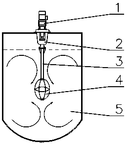
[0020] Such as figure 1 and figure 2 As shown, a stirring device according to an embodiment of the present invention includes a driving device 1, a transmission shaft 3 and a lantern-shaped impeller 4, one end of the transmission shaft 3 is connected to the driving device 1, and the other end of the transmission shaft 3 is connected to the impeller 4 .

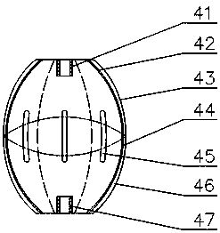
[0021] In the stirring device of this embodiment, the impeller 4 is set in a lantern shape, so that when the impeller 4 rotates, flow is formed in the upper part and the lower part respectively, and convection is formed at the junction of the upper part and the lower part (that is, the parting surface of the impeller 4). In this way, it can be fully mixed and sti...


PUM


Abstract

The invention discloses a stirring device. The stirring device comprises a driving device, a transmission shaft and a lantern-shaped impeller, wherein one end of the transmission shaft is connected with the driving device, and the other end of the transmission shaft is connected with the impeller. The stirring device can fully mix and stir, and does not have stirring dead corners, so that the stirring effect is improved.

Description

technical field [0001] The invention belongs to the technical field of chemical machinery, and in particular relates to a stirring device. Background technique [0002] The mixer is widely used in the chemical process for mixing and mixing liquid-solid, liquid-liquid, liquid-vapor two-phase and solid-liquid-vapor three-phase media in various physical and chemical processes. Chemical processes have a big impact. The mixer is vertically installed in the tank, and usually includes a driving device, a frame, a transmission shaft and an impeller. The impeller rotates with the transmission shaft to perform work on the mixed liquid for stirring and mixing. But the mixer of existing structure has the following problems: because the impeller has a certain distance from the bottom of the tank body, the stirring effect at the bottom of the tank is poor, which affects the physical or chemical process of the medium; when the tank body is very high, its drive shaft will also When the mi...

Claims


Application Information

Patent Timeline
IPC IPC(8): B01F7/18B01F7/00B01F15/00
CPCB01F27/13B01F27/90B01F35/1452
Inventor 宋伟朱超云胡虹李冰峰
Owner NANJING POLYTECHNIC INSITUTE
Why Eureka
Try Eureka