Circulation type permanent magnetic stirrer

A permanent magnet agitator, circulating technology, applied in chemical instruments and methods, dissolving, mixers, etc., can solve the problems of small stirring range, short service life, uneven stirring, etc., and achieve simple and reliable transmission and long service life. , good heat dissipation effect

Inactive Publication Date: 2008-01-02
SHANDONG HUATE MAGNET TECH
View PDF4 Cites 0 Cited by
  • Summary
  • Abstract
  • Description
  • Claims
  • Application Information

AI Technical Summary

Problems solved by technology

Electromagnetic stirring uses the traveling wave magnetic field generated by multiple sets of coils to turn the non-ferrous metal melt to achieve the purpose of stirring. The disadvantages are: 1. Due to the small radiation area of ​​the traveling wave magnetic field on the melt, it is extremely Stirring dead angle is easy to occur, and the stirring uniformity is poor; 2. The heat dissipation method is to circulate cooling water in the hollow wire constituting the coil to dissipate heat. Due to the limitation of the diameter of the wire, the flow rate of cooling water is small and the heat dissipation effect is poor. Therefore, the electromagnetic stirrer only It can work intermittently, and the working time does not exceed half an hour each time; 3. High energy consumption, a 30-ton electromagnetic stirrer for a smelting furnace consumes 315 kilowatts of electricity per hour
Mechanical stirring is contact stirring. Due to the limitation of the size of the smelting furnace door, the stirring range is small, the stirring speed is low, and the stirring uniformity is poor.
Manual stirring is more primitive, and has the disadvantages of high labor intensity, low stirring speed, and uneven stirring
Chinese patent application number 200510099200.8 discloses a permanent magnetic stirring device in the application document. Although the device can realize the stirring of non-ferrous metal melt, its disadvantages are: 1. The design of the cooling system is unreasonable. After the empty tube is blown out, the permanent magnet is only cooled in a single layer. The permanent magnet is not isolated from the heat source, and the cooling effect is poor. The temperature of the permanent magnet is as high as above 100°C during operation. At such a high temperature, the permanent magnet is easy to demagnetize and has a short service life. ; 2. The power transmission device that drives the permanent magnet to rotate is a sprocket and a chain. Since the chain is horizontal, it is easy to sag, easy to break during work, and has a short service life; 3. The upper and lower sections of the rotating shaft are hollow shafts with low strength , short service life

Method used


Image

  • Circulation type permanent magnetic stirrer
  • Circulation type permanent magnetic stirrer
  • Circulation type permanent magnetic stirrer

Examples


Embodiment Construction

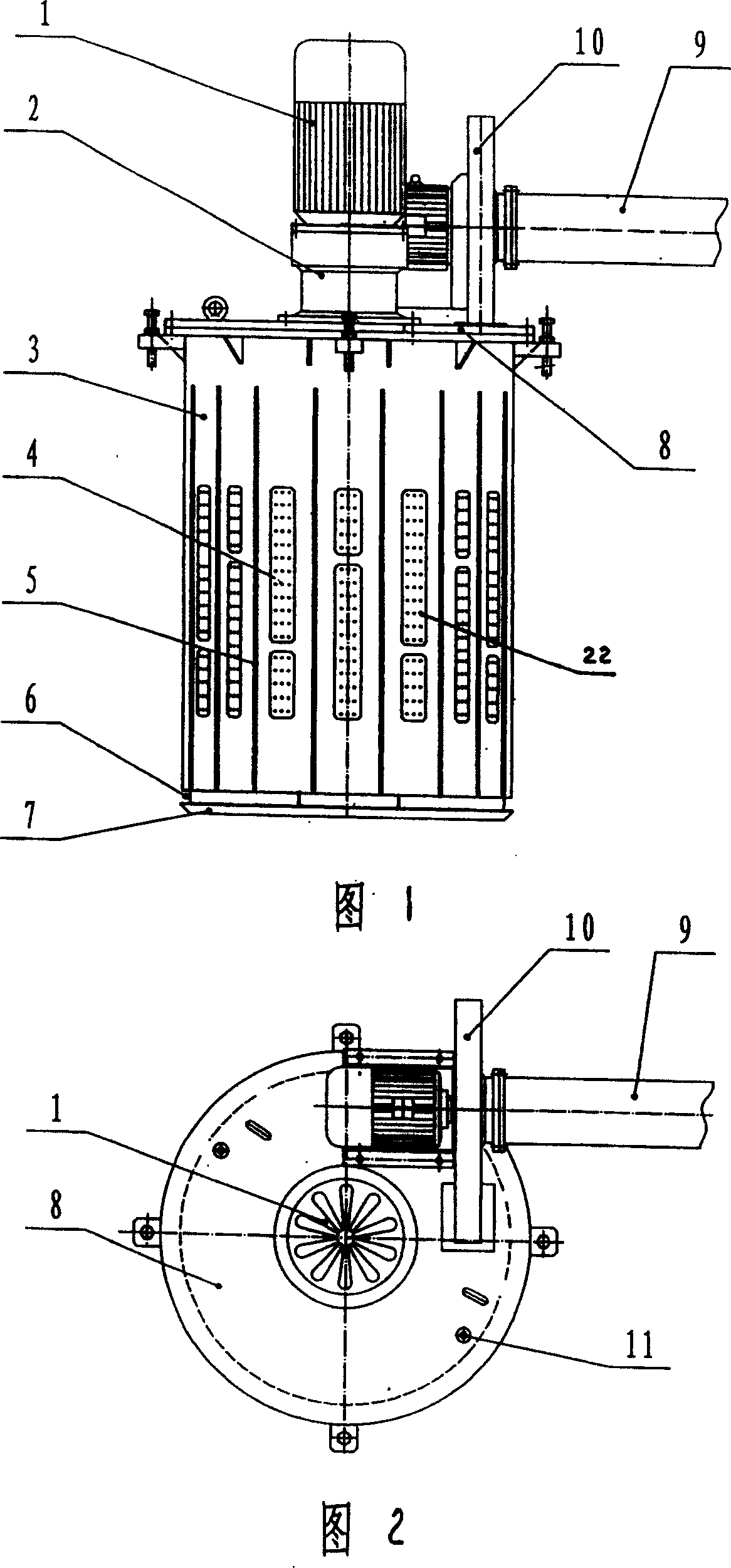
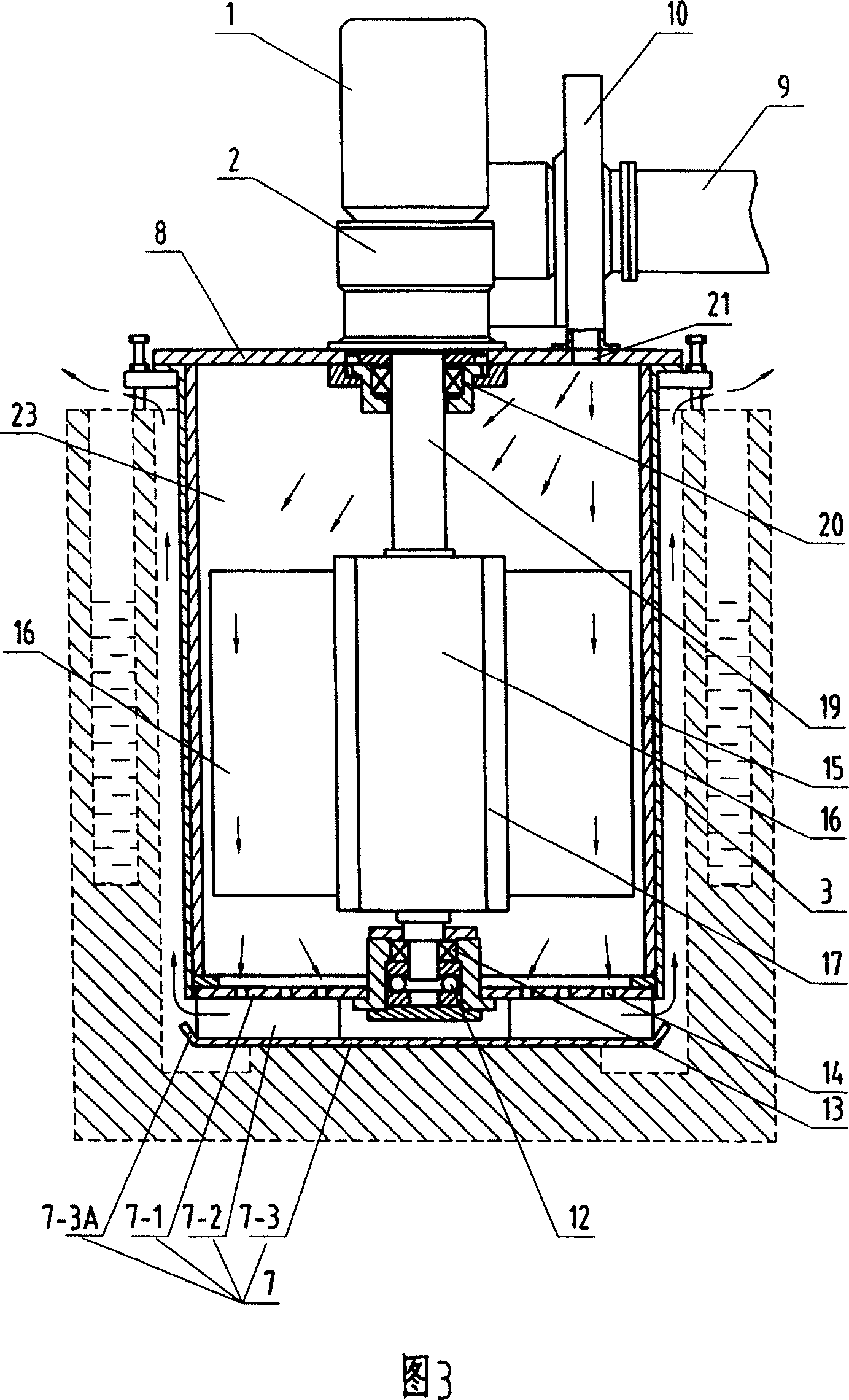
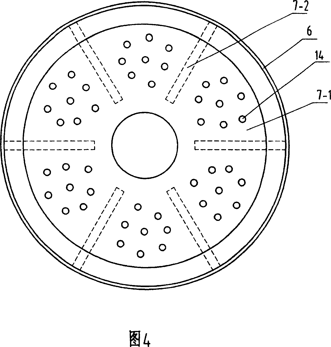
[0028] With reference to accompanying drawing, the circulating permanent magnetic stirrer described in the embodiment comprises chassis 7, the outer cover 3 that is made with non-magnetic material and is affixed with chassis 7, is coated with nonmetallic heat insulating layer 15 on the inner wall of outer cover 3 , the upper end of the outer cover 3 is fixedly connected with the upper end cover 8, and the inner cavity surrounded by the chassis 7, the outer cover 3 and the upper end cover 8 is the sensor cavity 23, which is installed on the chassis through the thrust ball bearing 12 and the cylindrical roller bearing 13. The rotating shaft 19 on the 7 and perpendicular to the chassis 7 protrudes through the inductor cavity 23 and the spherical roller bearing 20 on the upper end cover 8, and the motor 1 and the reducer 2 are directly shaft-coupled on the extending end of the rotating shaft 19, and the rotating shaft 19 is a solid shaft. On the upper end cover 8, a thermocouple 11...


PUM


Abstract

The invention relates the circulating magnetic stirrer. The inductor comprises chassis, enclosing cover and upper cover, the revolution axis on the chassis is through inductor, the motor and speed reducer direct axis are connected with out end of revolution axis, the draught fan is connected with the upper cover, the permanent magnet inducer is fixed in the inducer cavity, thermal resistance windows are installed on the enclosing cover, the board insulations are on the thermal resistance windows, on the board insulation there are holes, between thermal resistance windows there are wind-guiding bar, the chassis comprises outer bottom and inner bottom, between outer bottom and inner bottom there are bars which divides the chassis to form air-out grooves, and on every air-out grooves there are inner bottom air outlet. The device has the advantages of saving energy, good heat dissipation effect and long life.

Description

technical field [0001] The invention relates to a non-contact stirring device in non-ferrous metal smelting, more specifically a circulating permanent magnetic stirrer. Background technique [0002] In the smelting process of non-ferrous metals, it is necessary to stir the molten metal. According to the working mode of stirring, it is usually divided into three categories: electromagnetic stirring, mechanical stirring and manual stirring. Electromagnetic stirring uses the traveling wave magnetic field generated by multiple sets of coils to turn the non-ferrous metal melt to achieve the purpose of stirring. The disadvantages are: 1. Due to the small radiation area of ​​the traveling wave magnetic field on the melt, it is extremely Stirring dead angle is easy to occur, and the stirring uniformity is poor; 2. The heat dissipation method is to circulate cooling water in the hollow wire constituting the coil to dissipate heat. Due to the limitation of the diameter of the wire, th...

Claims


Application Information

Patent Timeline
Patent Type & Authority Patents(China)
IPC IPC(8): C22C1/02B01F13/08
Inventor 王兆连贾洪利刘风亮张洪彬
Owner SHANDONG HUATE MAGNET TECH
Why Eureka
Try Eureka