Eureka AIR delivers breakthrough ideas for toughest innovation challenges, trusted by R&D personnel around the world.

Gas production string used for gas reservoir

A technology for gas production pipes and gas reservoirs, which is applied in the direction of production fluid, earthwork drilling, wellbore/well components, etc., which can solve the problems of easy safety accidents and low safety and reliability, and achieve the effect of facilitating the gas-liquid separation process

Inactive Publication Date: 2018-03-20
陈磊
View PDF0 Cites 2 Cited by
  • Summary
  • Abstract
  • Description
  • Claims
  • Application Information

AI Technical Summary

Problems solved by technology

In the prior art, a straight nozzle is usually used, and the liquid obtains greater kinetic energy after being pressurized. After passing through the nozzle, the liquid will be ejected at a high speed. Under the interaction of the surface tension, viscosity and air resistance of the liquid, the liquid will The dripping, smooth flow, and wavy flow gradually change to the spray flow, and finally realize the two-phase separation of gas and liquid; but because the water flow discharged from the direct injection nozzle has surface tension, it needs to continuously flow downhole during the process of the liquid turning into a spray flow. Only by pressurizing can the liquid be ejected at a high speed and rub against the surrounding air to separate and atomize, and the higher the downhole air pressure, the lower the safety and reliability faced during gas production, which can easily lead to safety accidents

Method used


Image

  • Gas production string used for gas reservoir
  • Gas production string used for gas reservoir
  • Gas production string used for gas reservoir

Examples


Embodiment 1

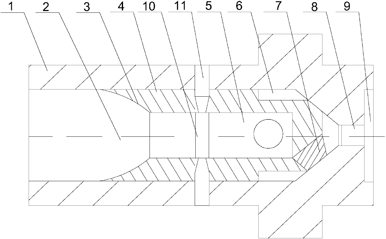
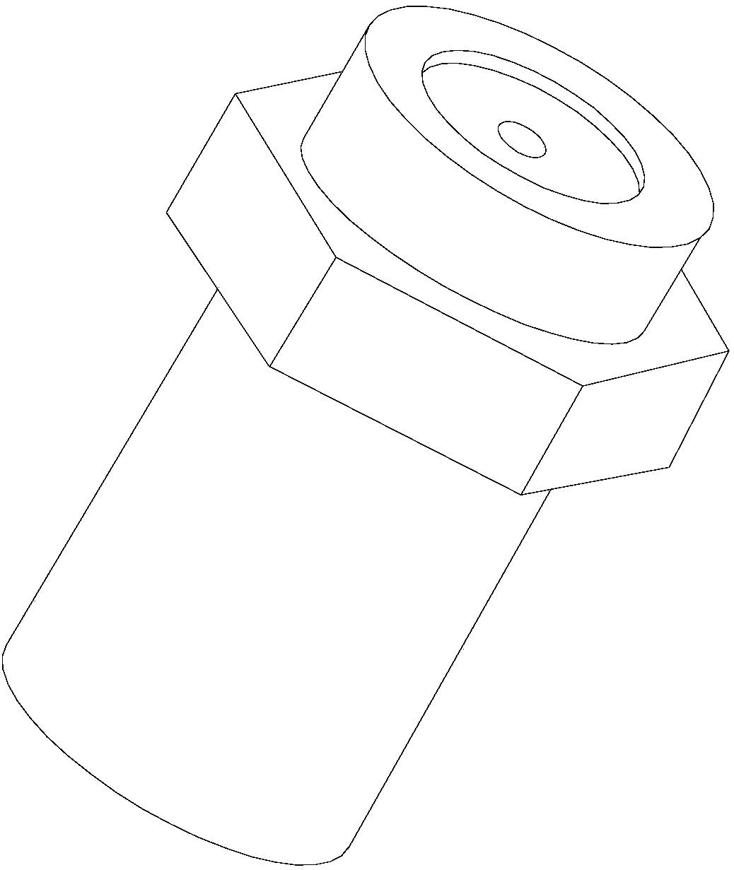
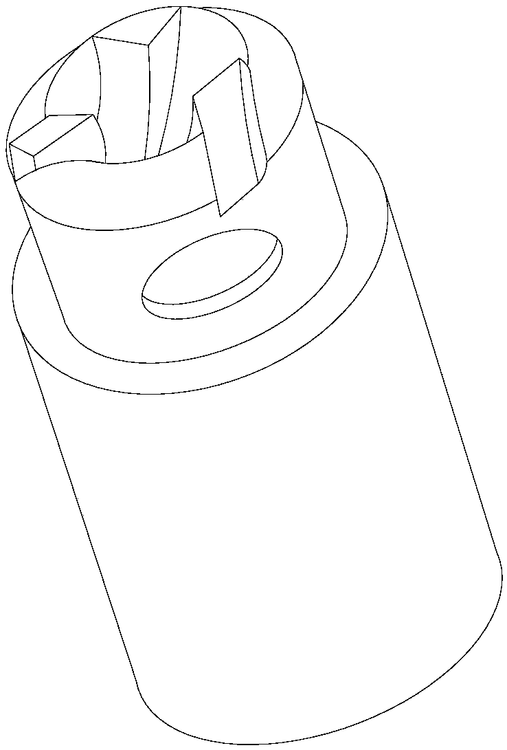
[0019] Such as Figure 1~3 As shown, this embodiment includes a core body 4 and a housing 1 sleeved outside the core body 4, the end of the housing body 1 is provided with a spray hole 8, and an inner conical surface 3 is provided at one end of the core body 4, and The inner conical surface 3 and the inner wall of the housing 1 form a cavity 2, and the other end of the core body 4 has a through hole facing the jet flow hole 8, and a plurality of swirl blades 7 are installed on the inner wall of the through hole, and the through hole It forms a swirl chamber 5 with the inner wall of the core 4; it also includes two air holes 11 passing through the shell 1 and the core 4, and an annular convection groove 10 is arranged in the middle of the core 4, and the two air holes 11 are symmetrically arranged in the convection Both ends of the groove 10, and the inner diameter of the air outlet end of the air hole 11 gradually decreases in the direction along the radial direction of the co...


PUM


Abstract

The invention discloses a gas production pipe string for a gas reservoir, which includes a core body and a casing. The end of the casing is provided with a jet hole, and an inner conical surface is arranged at one end of the core body. The inner conical surface and the inner wall of the casing form a cavity. The other end of the core body has a through hole facing the jet hole, and a plurality of swirl vanes are installed on the inner wall of the through hole. The through hole and the inner wall of the core body form a swirl flow cavity, and an annular convection groove is arranged in the middle of the core body. , and two air holes are symmetrically arranged at both ends of the convection tank. When the gas-liquid two-phase mixture in the gas well starts to rise under the push of the pressure in the well, the gas-liquid mixture enters the cavity and then compresses its volume through the inner conical surface, thereby increasing the flow velocity of the gas-liquid mixture. When entering the swirl cavity, the fluid and the swirl blades are in contact with each other, and the fluid is driven to rotate by the swirl blades, and finally the gas-liquid mixture is thrown out of the jet hole by the centrifugal force generated by the rotation.

Description

technical field [0001] The invention relates to the field of downhole gas production, in particular to a gas production pipe string for a gas reservoir. Background technique [0002] At the beginning of a small amount of liquid accumulation at the bottom of the gas well, the liquid in the wellbore can be taken out of the wellbore by the gas using its own upward force, and the gas well can still produce normally. The gas flow rate is called the liquid-carrying critical flow rate of the gas well; when the actual flow rate of the gas in the wellbore is lower than the critical flow rate, the gas flow cannot take the liquid in the well out of the wellhead by its own lifting force. In the prior art, a straight nozzle is usually used, and the liquid obtains greater kinetic energy after being pressurized. After passing through the nozzle, the liquid will be ejected at a high speed. Under the interaction of the surface tension, viscosity and air resistance of the liquid, the liquid w...

Claims


Application Information

Patent Timeline
IPC IPC(8): E21B43/12
CPCE21B43/124
Inventor 陈磊
Owner 陈磊
Why Eureka
Eureka Blog
Learn More