
Special multi-position output control structure for liquid flow

A liquid flow and control structure technology, applied in the direction of valve housing structure, multi-way valve, valve device, etc., can solve the problems of unable to meet the liquid flow control of complex structure, high maintenance cost, unfavorable wide use, etc., to achieve stable flow regulation Good performance, high assembly efficiency and low production cost

Inactive Publication Date: 2018-03-23
章小进
View PDF0 Cites 1 Cited by
  • Summary
  • Abstract
  • Description
  • Claims
  • Application Information

AI Technical Summary

Problems solved by technology

In some pipeline liquid conveying structures, it is sometimes necessary to control the conveying volume of liquid flow in different directions and different positions. The traditional switch valve structure can only perform simple switching and flow control in one direction, and cannot satisfy complex structures. liquid flow control
If multiple valve structures that cooperate with each other are used, although it can barely use the control of different flow transmission in different directions, it is very inconvenient to use, and the overall use cost is higher, and the later repair and maintenance costs are also higher, which is not conducive to widely used

Method used


Image

  • Special multi-position output control structure for liquid flow
  • Special multi-position output control structure for liquid flow
  • Special multi-position output control structure for liquid flow

Examples


Embodiment Construction

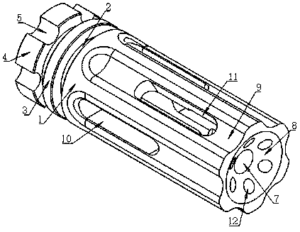
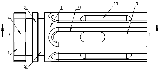
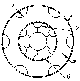
[0018] like Figure 1 to Figure 7 As shown, a special liquid flow multi-position output control structure can be assembled at the interface position of the pipeline structure. When the transfer pipelines in different directions are installed at the pipeline interface position, the control structure can easily realize different directions in different directions. Flow size control,

[0019] It is more convenient to use and can meet the requirements that the traditional switch valve structure cannot meet. This part is more convenient to use, and the tightness of the assembly connection is better. The flow rate of the output position is adjusted through the output hole structure of the spherical structure, so that the liquid is output. The speed can be adjusted freely, and the production cost is lower, and the effect of controlling the liquid flow is better. It includes a cylindrical control structure main body 1, which is the main part of the control structure and is used to co...


PUM


Abstract

The invention relates to the technical field of liquid conveying equipment, in particular to a special liquid flow multi-position output control structure. The technical solution adopted by the present invention is: comprising a cylindrical control structure main body, the left side of the control structure main body is provided with an integrally formed engaging connecting column, and the center position of the left end face of the engaging connecting column is provided with a second engaging assembly column, The center position between the second engaging assembly column and the main body of the control structure is provided with a cylindrical first engaging assembly column, and the left center of the second engaging assembly column is provided with a cylindrical main input hole, and the right side of the main input hole is A cylindrical main output hole is provided, and a flow control groove is arranged on the outer cylindrical surface of the main body of the control structure, and first liquid delivery holes and second liquid delivery holes are alternately arranged on the flow control grooves. The invention has the advantages of more convenience in use, better flow regulation stability, more convenient assembly operation, higher assembly efficiency, lower production cost and better effect of controlling liquid flow.

Description

technical field [0001] The invention relates to the technical field of liquid conveying equipment, in particular to a special liquid flow multi-position output control structure. Background technique [0002] The liquid needs to use the on-off valve structure in the process of conveying, and the speed of liquid conveying can be controlled through the on-off valve structure. In some pipeline-like liquid transport structures, it is sometimes necessary to control the transport volume of liquid flow in different directions and positions. The traditional switch valve structure can only perform simple switching and flow control in one direction, and cannot satisfy complex structures. liquid flow control. If multiple valve structures that cooperate with each other are used, although it can barely use the control of different flow transmission in different directions, it is very inconvenient to use, and the overall use cost is higher, and the maintenance cost in the later period is...

Claims


Application Information

Patent Timeline
Patent Type & Authority Applications(China)
IPC IPC(8): F16K11/085F16K27/06
CPCF16K11/085F16K27/065
Inventor 章小进
Owner 章小进
Learn More