
A network fault detection method and system

A network failure and network connection technology, applied in the field of computer networks, can solve the problems of incomplete network topology coverage, low accuracy, and difficulty in comprehensive utilization of detection data, so as to reduce the amount of calculation and system resource consumption, speed up fault response time, and automatically The effect of adapting to changes in network topology

Active Publication Date: 2021-01-29
CHEZHI HULIAN BEIJING SCI & TECH CO LTD
View PDF6 Cites 0 Cited by
  • Summary
  • Abstract
  • Description
  • Claims
  • Application Information

AI Technical Summary

Problems solved by technology

[0003] A variety of reasons lead to communication quality problems across the computer room intranet, such as network cards, network cables, servers and other single equipment failures. The individual probability of such failures is very small, but after multiplying the huge base, it cannot be ignored, and the single point of failure of the switch, network congestion, etc. , Dedicated line failures, etc. also occur frequently, so failures are almost unavoidable, so it is necessary to monitor the network quality across computer rooms and locate faults in a timely and accurate manner, which is very important to ensure the normal operation of the company's business
[0004] Existing network fault detection solutions are mostly divided into two categories. One is to manually locate the fault. After the problem has occurred, the operation and maintenance engineer will gradually narrow down the scope based on experience to troubleshoot suspicious lines, switches or servers. It is time-consuming and laborious and lacks data support. The accuracy is low, and the other is to actively detect the network status by deploying probes on all online servers, but there are problems that the network topology coverage is incomplete and the detection data is difficult to comprehensively utilize

Method used


Image

  • A network fault detection method and system
  • A network fault detection method and system
  • A network fault detection method and system

Examples


Embodiment Construction

[0032] Exemplary embodiments of the present disclosure will be described in more detail below with reference to the accompanying drawings. Although exemplary embodiments of the present disclosure are shown in the drawings, it should be understood that the present disclosure may be embodied in various forms and should not be limited by the embodiments set forth herein. Rather, these embodiments are provided for more thorough understanding of the present disclosure and to fully convey the scope of the present disclosure to those skilled in the art.

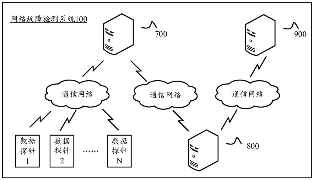
[0033] figure 1 A schematic diagram of a network fault detection system 100 according to an embodiment of the present invention is shown. a, figure 1 The network fault detection system 100 in is only exemplary, and in specific practical situation, there can be different numbers of network servers, aggregation servers, database servers and data probes in the network fault detection system 100, the present invention is to the networ...


PUM


Abstract

The invention discloses a network fault detection method and system. The method is suitable for being executed in an aggregation server; the aggregation server is in communication connection with oneor more network servers and a database server; the network servers are accessed to multiple Internet data centers; each Internet data center is deployed with multiple switches; multiple hosts are accessed to each switch; and a corresponding data probe is preset in each host and is in communication connection with the network server. The method comprises steps: one or more index data reported by the network server are received, wherein the index data are formed by the network server according to a detection result reported by each data probe; according to the index data in an abnormal state, anetwork connection is detected; and if the detection result indicates the network connection fails, an alarm is given; the index data with normal states are subjected to aggregation calculation to acquire corresponding network quality data; and the network quality data are transmitted to the database server for being stored conveniently.

Description

technical field [0001] The invention relates to the field of computer networks, in particular to a network fault detection method and system. Background technique [0002] Internet companies often have tens of thousands of servers. These servers are distributed in multiple computer rooms across the country and are connected to each other to form a company intranet. There are extensive network communications between computer rooms and between servers in the intranet, so the importance of communication quality is self-evident. [0003] A variety of reasons lead to communication quality problems across the computer room intranet, such as network cards, network cables, servers and other single equipment failures. The individual probability of such failures is very small, but after multiplying the huge base, it cannot be ignored, and the single point of failure of the switch, network congestion, etc. , Dedicated line failures, etc. also occur from time to time, so failures are a...

Claims


Application Information

Patent Timeline
Patent Type & Authority Patents(China)
IPC IPC(8): H04L12/24H04L12/26
CPCH04L41/0631H04L43/04H04L43/0811
Inventor 杨龙王金龙邓谦
Owner CHEZHI HULIAN BEIJING SCI & TECH CO LTD
Learn More