Assembling structure of lamp holder and bulb

An assembly structure and light bulb technology, applied to lighting devices, components of lighting devices, light source fixing, etc., can solve the problems of easy electric shock, potential safety hazards, troublesome bulb replacement, etc., and achieve the effect of convenient replacement and avoiding electric shock accidents

Active Publication Date: 2018-03-27
HEHONG ELECTRICAL CO LTD
View PDF9 Cites 5 Cited by
  • Summary
  • Abstract
  • Description
  • Claims
  • Application Information

AI Technical Summary

Problems solved by technology

[0002] At present, the light bulb is generally connected to the lamp holder by screw connection. When the bulb is damaged, the old bulb needs to be unscrewed from the lamp holder, and the new bulb should be screwed onto the lamp holder; When the lamp holder is still connected to the power supply, once the human body comes into contact with the conductive sheet in the lamp holder, it is easy to get an electric shock, and there is a great potential safety hazard. Unscrews, has the disadvantage of troublesome bulb replacement

Method used


Image

  • Assembling structure of lamp holder and bulb
  • Assembling structure of lamp holder and bulb
  • Assembling structure of lamp holder and bulb

Examples


Embodiment Construction

[0013] The specific embodiments of the present invention will be further described in detail below in conjunction with the accompanying drawings.

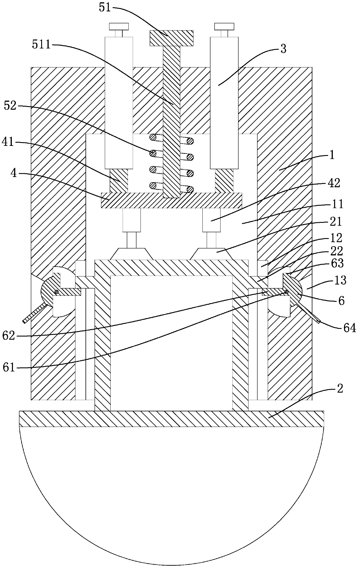
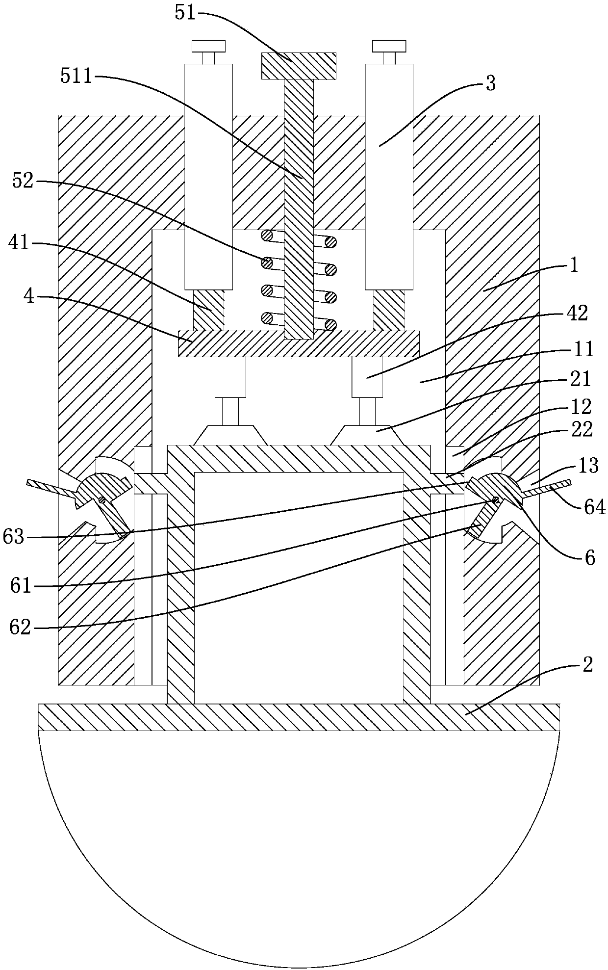
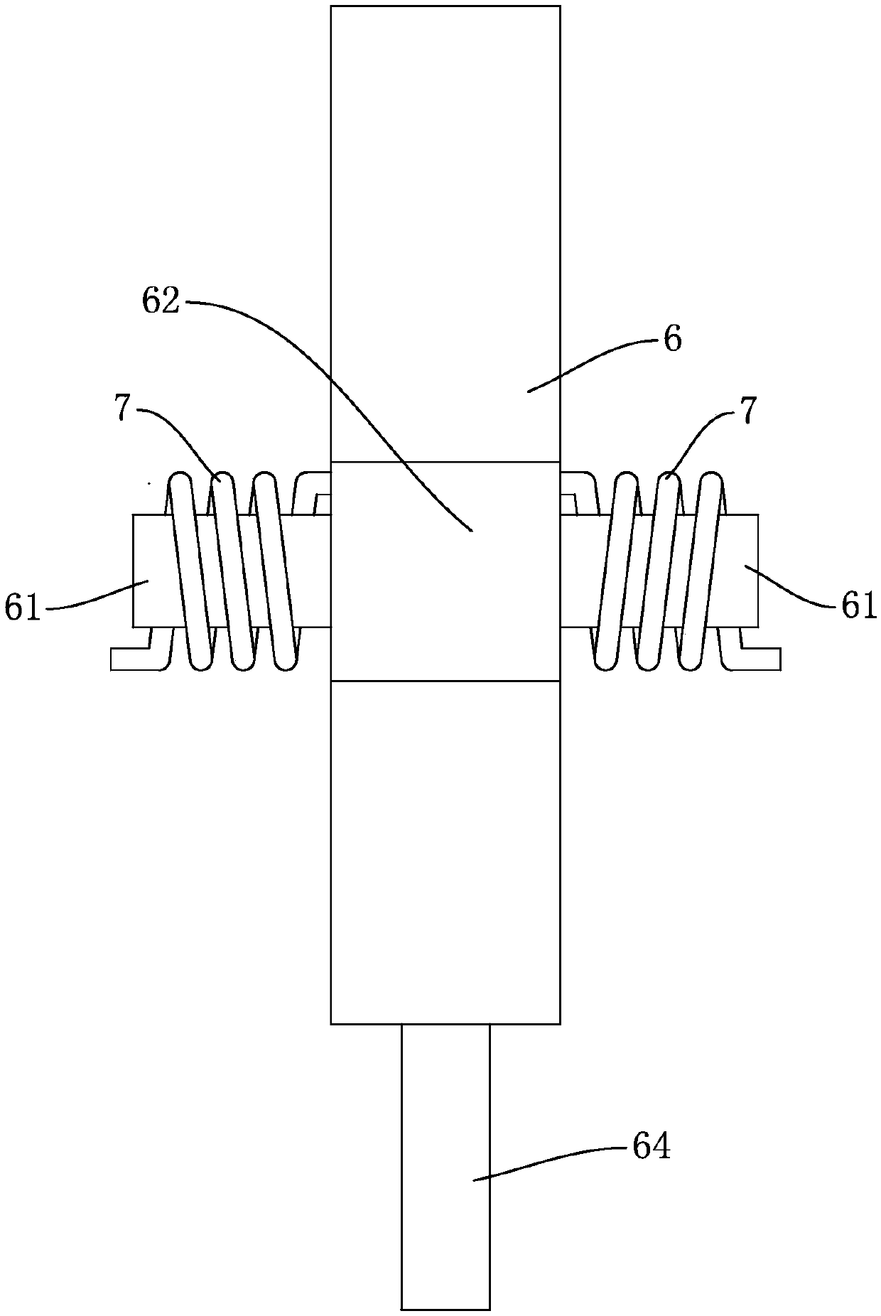
[0014] An assembly structure of a lamp holder and a light bulb, comprising a case 1 with a cavity 11 inside and an open bottom end, a light bulb 2 is installed on the case 1, the upper end of the light bulb 2 is inserted into the cavity 11, and the cover 1 A pair of terminal posts 3 are fixed on the top, and the terminal posts 3 extend into the cover case 1 after penetrating the cover case 1. A circuit board 4 is arranged in the cover case 1 above the bulb 2, and a circuit board 4 is fixed on the upper end surface of the circuit board 4 for wiring. A pair of conductive contacts 41 are fixed on the lower end of the column 3 to achieve electrical connection, and a pair of elastic conductive pins 42 are fixed on the lower end surface of the circuit board 4 to abut against the contact 21 on the upper end of the bulb 2 to achieve electri...


PUM


Abstract

The invention discloses an assembling structure of a lamp holder and a bulb. The assembling structure comprises a casing. The bulb is installed on the casing. A pair of binding posts are fixed to thetop of the casing. A circuit board is arranged inside the casing and further located above the bulb. Conductive contacts are fixed to the upper end face of the circuit board. Elastic conductive needles are fixed to the lower end face of the circuit board. A driving structure is installed on the casing. Bosses are arranged on the outer walls of the two sides of the bulb. Sliding chutes capable of allowing the bosses to slide in are arranged on the inner side wall of the casing. Mounting cavities communicating with the corresponding sliding chutes are formed in the casing and located in the outer sides of the sliding chutes. Rotating blocks are connected into the corresponding mounting cavities in a rotatable mode. Lugs are arranged on the outer side walls of the rotating blocks. Torsional springs are arranged outside rotating shafts in a sleeving mode and further located at the front sides and the rear sides of the rotating blocks, and protruding edges are arranged on the outer side walls of the rotating blocks. Turning handles are arranged on the side walls, facing the outer sides, of the rotating blocks. When the bulb is replaced, electric shock accidents can be effectively avoided. Moreover, screwing of the bulb is not required, and thus convenience can be brought about to replacement of the bulb.

Description

technical field [0001] The invention belongs to the technical field of electrical devices, and relates to an assembly structure of a lamp holder and a bulb. Background technique [0002] At present, the light bulb is generally connected to the lamp holder by threaded connection. When the bulb is damaged, the old bulb needs to be unscrewed from the lamp holder, and the new bulb should be screwed onto the lamp holder; When the lamp holder is still connected to the power supply, once the human body comes into contact with the conductive sheet in the lamp holder, it is easy to get an electric shock, and there is a great potential safety hazard. When replacing the bulb, the bulb needs to be screwed on Unscrewed, there is a disadvantage of troublesome bulb replacement. Contents of the invention [0003] In order to solve the above problems, the present invention designs an assembly structure of a lamp holder and a bulb, which can effectively avoid electric shock accidents and b...

Claims


Application Information

Patent Timeline
Patent Type & Authority Applications(China)
IPC IPC(8): F21V19/00F21V17/12F21V17/10
CPCF21V17/10F21V17/12F21V19/00
Inventor 沈惠萍
Owner HEHONG ELECTRICAL CO LTD
Why Eureka
Try Eureka