Device for measuring fill level of liquid in container with ultrasonic sensor

A technology for ultrasonic sensors, filling levels, applications in measuring devices, material analysis using acoustic/ultrasonic/infrasonic waves, sound-generating instruments, etc.

Active Publication Date: 2018-04-03
HELLA KGAA HUECK & CO
6 Cites 0 Cited by

AI-Extracted Technical Summary

Problems solved by technology

The fill level in the sound absorbing cup corresponds here to the filling level outside the sound absorb...

Method used

[0018] The front chamber 13 extends over approximately 20% to 25% of the height of the inner housing 3. The inner housing 3 has a plurality of protruding contact regions 20 , two opposite contact regions 20 being visible here. These contact regions 20 are placed on the measuring tube 9 of the inner housing 3 and extend as far as the inner wall of the outer housing 2 . The inner housing 3 thus has a fixed seat in the outer housing 2 . In particular, the relatively protruding contact regions of the outer housing 2 have corresponding grooves, which are not visible here. The inner housing 3 can thus be inserted firmly from below into the outer housing 2 and fitted there in a pluggable manner. Ventilation openings 23 are also provided in the region of the upper boundary of the measuring tube 9 , through which a pressure equalization can be achieved as the liquid level rises. In the region of the lower end, the wall 22 of the antechamber 13 , which is part of the inner housing 3 , is chamfered and forms the bevel 17 . The bevel of the measuring tube 9 is directe...

Abstract

In a device for measuring a fill level of a liquid in a container with an ultrasonic sensor which is arranged on a floor element, wherein a damping cup with a measuring tube is assigned to the ultrasonic sensor, the damping cup has an external housing and an internal housing. The internal housing contains the measuring tube, and either the internal housing has outwardly protruding contact elementsthat lie against the inside of the external housing or the external housing has outwardly protruding contact elements that lie against the outside of the internal housing. The external housing is also provided and designed for pluggable mounting of the internal housing, and a channel is formed between the internal housing and the external housing.

Application Domain

Material analysis using sonic/ultrasonic/infrasonic wavesVibration measurement in fluid +4

Technology Topic

EngineeringElectrical and Electronics engineering +2

Image

  • Device for measuring fill level of liquid in container with ultrasonic sensor
  • Device for measuring fill level of liquid in container with ultrasonic sensor

Examples

  • Experimental program(1)

Example Embodiment

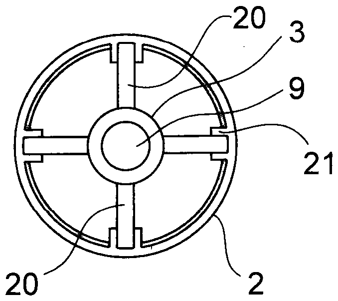
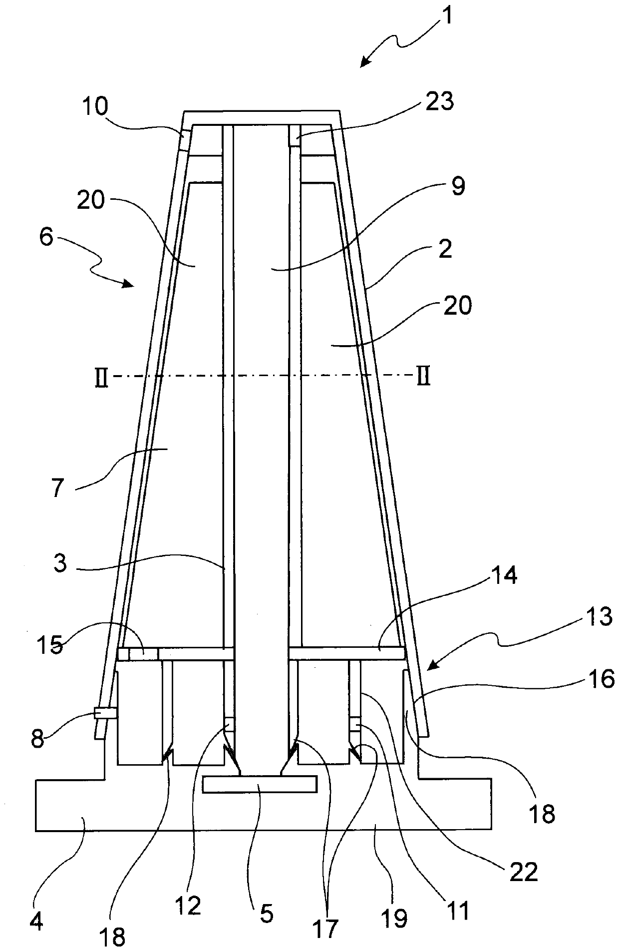
[0017] exist figure 1 The device 1 is shown in a cut-away side view. The device 1 basically consists of the sound-absorbing cup 6 and the base element 4 , which in the present embodiment is configured as a flange 19 . An ultrasonic sensor 5 is integrated in the base element 4 or arranged thereon. The base element 4 is formed here as a flange 19 , and it is also evident that the flange 19 projects laterally beyond the structural surface of the sound-absorbing cup 6 in order to form a fastening region here. Extending over the ultrasonic sensor 5 is a measuring tube 9 in which the actual measurement takes place. The ultrasonic sensor 5 emits ultrasonic waves, which propagate upwards in the measuring tube 9 , are reflected at the interface liquid/air and are then received again by the ultrasonic sensor 5 as reflected ultrasonic waves. From the travel time of the ultrasonic waves it is then possible to calculate the distance of the ultrasonic sensor 5 to the interface and thus the filling level. The measuring tube 9 is part of the inner housing 3 . The inner housing 3 also forms the main part of the lower region of the muffler cup 6 in which the front chamber 13 is formed. The outermost wall of the front chamber 13 is formed by the outer casing 2 . Furthermore, the antechamber 13 is formed by the wall of the measuring tube 9 , the wall 22 formed in the inner housing 3 and the upper boundary 14 formed by the inner casing 3 . This upper boundary 14 closes the front chamber 13 upwards. The front chamber 13 is closed downwards by the bottom element 4 .
[0018] The front chamber 13 extends over approximately 20% to 25% of the height of the inner casing 3 . The inner housing 3 has a plurality of protruding contact regions 20 , of which two opposite contact regions 20 can be seen here. These contact areas 20 are placed at the measuring tube 9 of the inner housing 3 and extend as far as the inner wall of the outer housing 2 . The inner housing 3 thus has a fixed seat in the outer housing 2 . In particular, the relatively protruding contact areas of the outer housing 2 have corresponding grooves, which are not visible here. In this way, the inner housing 3 can be pushed into the outer housing 2 in a fixed position from below and can be assembled there so as to be pluggable. A ventilation opening 23 is also provided in the upper boundary region of the measuring tube 9 , by means of which a pressure equalization can be achieved when the liquid level rises. In the lower end region, the wall 22 of the antechamber 13 , which is part of the inner housing 3 , is chamfered and forms a slope 17 . The slope of the measuring tube 9 points outwards and the slope of the wall 22 points inwardly, ie opposite to the adjacent slope 17 of the inner housing 3 in the region of the measuring tube 9 . As a result, a reliable self-centering at the corresponding inclination 18 of the base element 4 is achieved. The outer casing 2 surrounds the inner casing 3, but is not fully configured downwards so wide or deep that the inner casing 3 protrudes slightly downwards from the outer casing 2. This simplifies installation. An inlet opening 8 is provided in the lower region of the outer housing 2 , through which inlet opening 8 liquids, in particular oil, enter through the wall of the outer housing 2 and then into the region of the front chamber 13 of the inner housing 3 . In this lower region the outer casing 2 forms part of the outer wall of the antechamber 13 . The outer casing 2 has a ventilation opening 10 vertically above the access opening 8 . Between this inlet opening 8 and the ventilation opening 10 a channel 7 is formed, through which channel 7 the rapidly injected foam can be discharged again directly, if possible.
[0019] in the attached figure 2shown along the figure 1 The line II-II of . passes through the cross-section of the device 1 , in particular the muffler cup 6 . In the middle, the measuring tube 9 can be seen, which is part of the inner housing 3 . The four protruding contact areas 20 start from the measuring tube 9 at an angle of 90°. The protruding contact areas 20 are guided and received in corresponding grooves 21 of the outer housing 2 .
[0020] In the operating mode, the liquid or oil enters through the inlet opening 8 into the outer casing 2 , in particular then into the outermost ring of the antechamber 13 formed between the outer casing 2 and the inner casing 3 . The liquid flows in this outer ring and then enters the inner ring of the antechamber 13 through the inlet opening 11 formed in the wall 22 of the inner housing 3 . The liquid must then circulate around the inner ring again by at least 180° so that it can then enter the actual measuring tube 9 through the inlet opening 12 . On this path through the outer and inner rings of the antechamber 13, the liquid is vented as much as possible. In the measuring tube 9 the level of the liquid rises and falls corresponding to the level outside the device 1 . In order to achieve this, ventilation openings 23 are provided at the upper boundary of the measuring tube 9 , through which ventilation openings 23 the air can escape and then also through ventilation openings in the outer housing 2 on the opposite side. 10 escapes. In the case of a volume that is rapidly entered through an access opening 8 in the outer casing 2 or in particular also foam, it can escape directly through the channel 7 formed between the inner casing 3 and the outer casing 2 . In this case, the foam passes through the recess 15 in the upper protruding boundary 14 of the inner housing 3 and reaches the channel 7 formed between the inner housing 3 and the outer housing 2 and then passes over the outer housing Ventilation opening 10 in 2 escapes.
[0021] All the features mentioned in the preceding description and in the claims can be combined in any choice with the features of the independent claims. The disclosure of the invention is therefore not limited to the described or claimed feature combinations, on the contrary, all feature combinations that are significant within the scope of the invention are to be regarded as disclosed.

PUM

no PUM

Description & Claims & Application Information

We can also present the details of the Description, Claims and Application information to help users get a comprehensive understanding of the technical details of the patent, such as background art, summary of invention, brief description of drawings, description of embodiments, and other original content. On the other hand, users can also determine the specific scope of protection of the technology through the list of claims; as well as understand the changes in the life cycle of the technology with the presentation of the patent timeline. Login to view more.
Why Eureka
Try Eureka