
Upper limb strength training device in sports equipment

A training device and sports equipment technology, applied in gymnastics equipment, muscle training equipment, sports accessories, etc., can solve the problems of lengthening or shortening, unable to meet the needs of use, and single training method, so as to ensure comfort and improve use. Safety and the effect of ensuring rationality

Inactive Publication Date: 2018-04-10
HUNAN UNIV OF ARTS & SCI
View PDF12 Cites 3 Cited by
  • Summary
  • Abstract
  • Description
  • Claims
  • Application Information

AI Technical Summary

Problems solved by technology

[0002] In the prior art: the patent with the authorized publication number CN 206597267 U discloses a device for training upper limb strength in sports equipment, including a fixed cover and a telescopic cover, and a screw is inserted on the opposite side of the opening side of the fixed cover, and the inner part of the screw is The end is located in the fixed cover, and the outer end of the screw is threaded with a spiral ring. There are several springs in the fixed cover and the telescopic cover. One end of the spring is fixed on the inner wall of the opposite side of the opening side of the telescopic cover. At the inner end of the screw, the spring is parallel to the telescopic movement direction of the telescoping cover. When the spiral ring is rotated, the spring can be stretched or shortened. The training device also includes a pair of hand-held components located on both sides of the screw. The hand-held component includes a rectangular base Rod, the inner end of the base rod is inserted into the fixed cover and fixed on the opposite side of the opening side of the telescopic cover, the outer end of the base rod passes through the fixed cover and the end is threaded with an adjustment rod, and the other end of the adjustment rod is clamped with a Ring pull, its training method is relatively simple, can not meet the needs of use

Method used


Image

  • Upper limb strength training device in sports equipment
  • Upper limb strength training device in sports equipment
  • Upper limb strength training device in sports equipment

Examples


Embodiment Construction

[0032] The technical solutions in the embodiments of the present invention will be clearly and completely described below with reference to the accompanying drawings in the embodiments of the present invention. Obviously, the described embodiments are only a part of the embodiments of the present invention, but not all of the embodiments. Based on the embodiments of the present invention, all other embodiments obtained by those of ordinary skill in the art without creative efforts shall fall within the protection scope of the present invention.

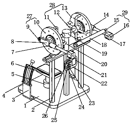
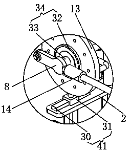
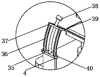
[0033] see Figure 1-3 , The present invention provides a technical solution: an upper limb strength training device in sports equipment, comprising a counterweight base (1), a first support frame (3) is fixed on the side of the counterweight base (1), and the first support frame ( 3) There are two groups, the two groups of first support frames (3) are arranged symmetrically on the left and right, and the end of the first support fram...


PUM


Abstract

The invention discloses an upper limb strength training device in sports equipment. The training device comprises a balance weight base, wherein first support frames are fixed to the side faces of thebalance weight base; the two groups of first support frames are arranged in a mode of being laterally symmetrical, and first mounting bases are connected to the ends of the first support frames; andtension training devices are arranged on the first mounting bases. In a training process, by virtue of handles which are held in the hands of a trained object, first sliding blocks are driven to slideon sliding rails, and tension springs are pulled by virtue of the first sliding blocks, so that counter-acting force generates on the first sliding blocks through tensile deformation of the tension springs, and subsequently, a purpose of training upper limbs is achieved; the sliding rails are of arc-shaped structures, which conforms to the concept of human mechanics design, so that the rationality of the design is guaranteed; and rubber heads are arranged at the ends of the sliding rails, so that the trained object is protected from getting hurt by the sliding rails, and the using safety of the upper limb strength training device is greatly enhanced.

Description

technical field [0001] The invention relates to the technical field of sports equipment, in particular to an upper limb strength training device in sports equipment. Background technique [0002] In the prior art: the patent with the authorized publication number of CN 206597267 U discloses a strength training device for upper limbs in sports equipment, including a fixed cover and a telescopic cover. The end is located in the fixed cover, the outer end of the screw is screwed with a threaded ring, and there are several springs in the fixed cover and the telescopic cover. At the inner end of the screw rod, the spring is parallel to the direction of the telescopic movement of the telescopic cover, and the spring can be elongated or shortened when the spiral ring is rotated. Rod, the inner end of the base rod is inserted into the fixed cover and fixed on the opposite side of the opening side of the telescopic cover, the outer end of the base rod passes through the fixed cover ...

Claims


Application Information

Patent Timeline
IPC IPC(8): A63B23/12A63B17/00A63B21/055A63B71/06
CPCA63B17/00A63B21/0552A63B23/12A63B23/1218A63B71/0605A63B2225/09A63B2225/20A63B2225/50
Inventor 李小华李剑波李果郭玉凤邓小康陈锋泰
Owner HUNAN UNIV OF ARTS & SCI
Learn More