
Bi-directional backstop capable of meeting high-speed rotation requirement

A two-way backstop, high-speed rotation technology, applied in the direction of one-way clutches, clutches, mechanical equipment, etc., can solve the problems that the speed cannot reach tens of thousands of revolutions per minute, the requirements for matching parts are high, and the backstop function cannot be realized.

Inactive Publication Date: 2018-04-17
东莞东晟磁电磁控技术有限公司
View PDF0 Cites 2 Cited by
  • Summary
  • Abstract
  • Description
  • Claims
  • Application Information

AI Technical Summary

Problems solved by technology

[0002] The existing backstop mechanism generally adopts a cam structure, which has high requirements for the matching dimensions of the parts, and the speed cannot reach tens of thousands of revolutions per minute, and the backstop function under high-speed conditions cannot be realized

Method used


Image

  • Bi-directional backstop capable of meeting high-speed rotation requirement
  • Bi-directional backstop capable of meeting high-speed rotation requirement
  • Bi-directional backstop capable of meeting high-speed rotation requirement

Examples


Embodiment Construction

[0025] In order to further illustrate the technical means and functions adopted by the present invention to achieve the intended purpose, the specific implementation modes of the present invention will be described in detail below in conjunction with the accompanying drawings and preferred embodiments.

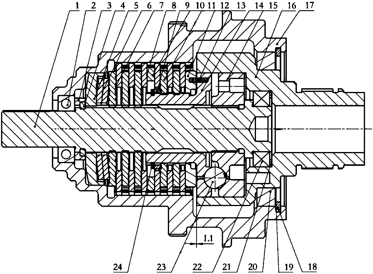
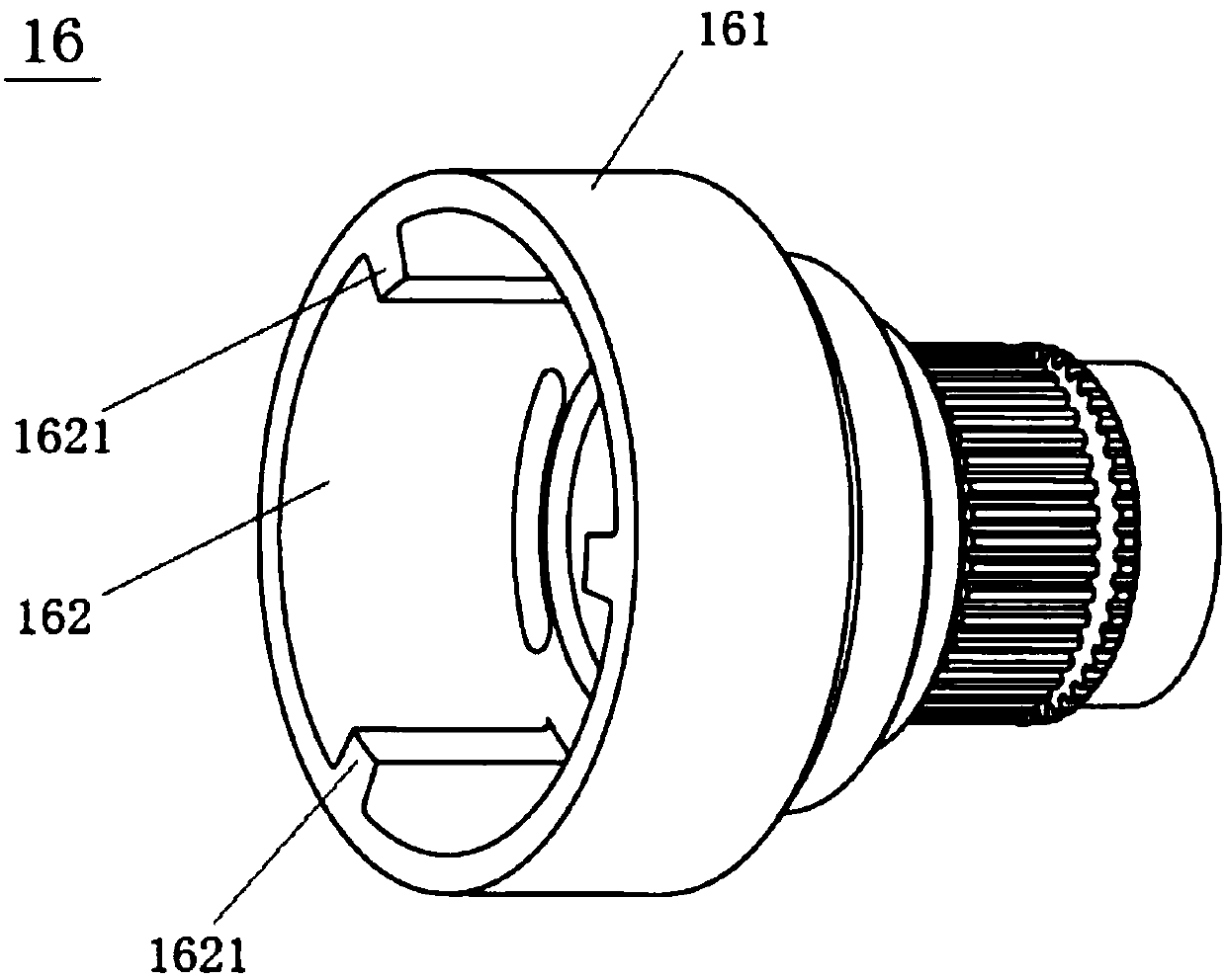
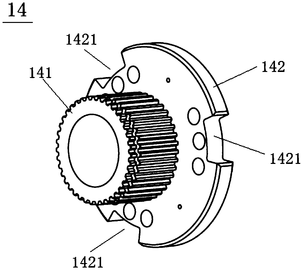
[0026] Please refer to Figure 1 to Figure 4 , the embodiment of the present invention provides a bidirectional backstop that satisfies high-speed rotation, including an input shaft 16, an output shaft 1 whose front end is inserted into the input shaft 16, and a casing that covers the input shaft 16 and the output shaft 1 17. An input ballway disk 14 sleeved on the periphery of the output shaft 1 and embedded in the port of the input shaft 16 at the front end, an output ballway disk 15 sleeved on the periphery of the front end of the output shaft 1 and embedded in the input shaft 16, sleeved on the input ballway A spring seat 12 on the periphery of the disk 14 and located on t...


PUM


Abstract

The invention discloses a bidirectional backstop satisfying high-speed rotation, comprising an input shaft, an output shaft, a housing, an input ballway disk, an output ballway disk, a spring seat, several compression springs, a dynamic and static friction plate group A and a dynamic and static friction plate group B. The rear part of the input shaft is the input sleeve, and there is a movable groove on the input sleeve, and several protruding shafts are protruded on the inner wall of the movable groove; the input ballway disk includes the input driving shaft, the input ballway disk body, and the input ballway disk There is a gap reserved between the rear end surface of the body and the spring seat; an input groove for the convex shaft to be inserted and moved is recessed on the outer edge of the input ballway disk body, and an input groove for the convex shaft to be inserted and moved is concavely provided on the outer edge of the output ballway disk. An active output groove; a number of steel balls are embedded in the front end of the input ballway disc body. The invention can realize the backstop function, achieve the function of transmitting torque from the input to the output, but the output cannot transmit the torque to the input, can not be limited by the rotational speed, and can meet the backstop function under high-speed conditions.

Description

technical field [0001] The invention relates to a backstop, in particular to a bidirectional backstop that satisfies high-speed rotation. Background technique [0002] The existing backstop mechanism generally adopts a cam structure, which requires high matching dimensions of the parts, and the speed cannot reach tens of thousands of revolutions per minute, so the backstop function under high-speed conditions cannot be realized. Contents of the invention [0003] In view of the above deficiencies, the object of the present invention is to provide a bidirectional backstop that satisfies high-speed rotation, realizes the backstop function, and achieves the function of transmitting torque from input to output, while the output cannot transmit torque to the input. At the same time, it can not be limited by the speed , to meet the high-speed condition of the backstop function. [0004] The technical scheme that the present invention adopts for achieving the above object is: ...

Claims


Application Information

Patent Timeline
IPC IPC(8): F16D41/064
CPCF16D41/064
Inventor 陈波
Owner 东莞东晟磁电磁控技术有限公司
Learn More