Bidirectional non-return bearing

A backstop bearing and axial technology, applied in the field of bearings, can solve problems such as inconvenience and difficulty in use, and achieve the effects of cost reduction, convenient disassembly and assembly, and simplified structure

Pending Publication Date: 2018-11-06
扬州久扬渔具有限公司
View PDF0 Cites 2 Cited by
  • Summary
  • Abstract
  • Description
  • Claims
  • Application Information

AI Technical Summary

Problems solved by technology

[0002] The existing one-way bearing can only realize the backstop function in one direction, and it is not easy to use when two-way backstop is required. When the backstop is realized in the other direction, it is necessary to replace the bearing or change the structure, which is very inconvenient to use

Method used


Image

  • Bidirectional non-return bearing
  • Bidirectional non-return bearing
  • Bidirectional non-return bearing

Examples


Embodiment Construction

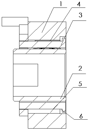
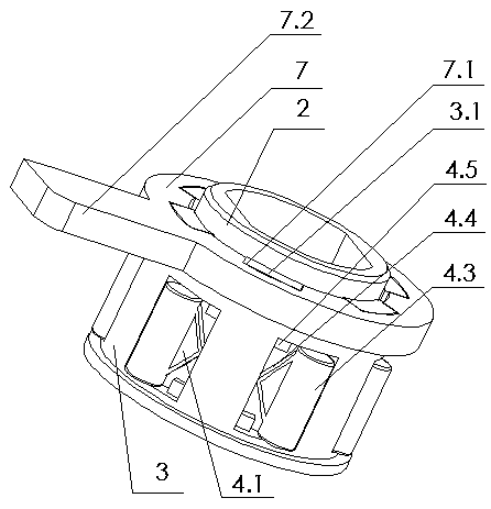
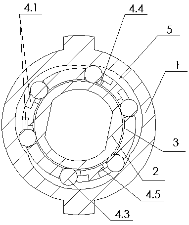
[0019] Such as figure 1 , 2 As shown, the present invention includes an outer cover 1, an inner cover 2 placed in the outer cover 1, and a cage 3 between the inner and outer covers 1 and 2, one end of the cage 3 cooperates with the outer cover 1 through a step 6, and the other end There are a plurality of bosses 3.1 that protrude from the jacket 1 in the circumferential direction, and are connected with paddles 7. The paddles 7 are ring-shaped, and the inner circumference is evenly distributed with grooves 7.1 that engage with the bosses 3.1. The paddles 7.1 One side is also connected with driving lever 7.2.

[0020] There are multiple groups of roller devices 4 evenly distributed around the cage 3, the roller devices 4 include two axial long holes 4.1 arranged on the outer wall of the cage 3, and the axial long holes 4.1 are respectively provided with rollers 4.3 and elastic sheets 4.4, the elastic sheet 4.4 is V-shaped, the opening ends of the elastic sheet 4 in the two ax...


PUM


Abstract

The invention relates to a bidirectional non-return bearing and relates to the field of bearings. The bidirectional non-return bearing comprises an outer sleeve, an inner sleeve placed in the outer sleeve and a retaining rack located between the inner sleeve and the outer sleeve. The bidirectional non-return bearing is characterized in that a plurality of pin roller devices are circumferentially and uniformly distributed on the retaining rack; each pin roller device comprises two axial long holes in the outer wall of the retaining rack, pin rollers and elastic sheets are separately arranged inthe axial long holes, and the elastic sheets of the two axial long holes lean against the corresponding pin rollers along opposite directions circumferentially; arc-shaped recess parts separately corresponding to the pin roller devices are circumferentially and uniformly arranged on the inner wall of the outer sleeve, the concave depths of the arc-shaped recess parts are gradually decreased fromthe middle part to two sides, one side of the retaining rack is connected to a pulling sheet, and the pulling sheet is used for rotating the retaining rack. According to the bidirectional non-return bearing provided by the invention, the non-return function of a single bearing in two directions can be achieved, and the size and other functions of the bearing are consistent to those of a single-direction bearing. In a structure to achieve bidirectional non-return, the bearing can be used directly, so that the unnecessary structure is simplified, and the cost is lowered.

Description

technical field [0001] The invention relates to the field of bearings, in particular to a bidirectional backstop bearing. Background technique [0002] Existing one-way bearings can only realize the backstop function in one direction, and are not easy to use when two-way backstop is required, and need to replace the bearing or change the structure when realizing backstop in the other direction, which is very inconvenient to use. Contents of the invention [0003] The purpose of the present invention is to provide a bidirectional backstop bearing, which can effectively solve the problems in the background technology. [0004] The technical solution to achieve the above purpose is: a bidirectional backstop bearing, including an outer sleeve, an inner sleeve placed inside the outer sleeve, and a cage between the inner sleeve and the outer sleeve. The roller device includes two axial long holes arranged on the outer wall of the cage, and rollers and elastic sheets are respect...

Claims


Application Information

Patent Timeline
Patent Type & Authority Applications(China)
IPC IPC(8): F16C19/26F16D41/066
CPCF16C19/26F16D41/064
Inventor 杨俊荣
Owner 扬州久扬渔具有限公司
Why Eureka
Try Eureka