Annular speed reduction device with non-return function

A deceleration device and ring-type technology, which is applied in the direction of transmission, transmission parts, belts/chains/gears, etc., can solve the problems of large installation site and space, many unit components, high manufacturing and use costs, etc.

Inactive Publication Date: 2016-05-04
HUNAN TECHUAN HEAVY IND TECH CO LTD
View PDF12 Cites 0 Cited by
  • Summary
  • Abstract
  • Description
  • Claims
  • Application Information

AI Technical Summary

Problems solved by technology

There are many unit components in the existing transmission system, not only the cost of manufacture and use is high, but also the place and space required for installation are large

Method used


Image

  • Annular speed reduction device with non-return function
  • Annular speed reduction device with non-return function
  • Annular speed reduction device with non-return function

Examples


Embodiment 1

[0050] Embodiment 1 (one shaft and two rings):

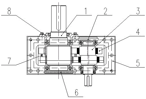
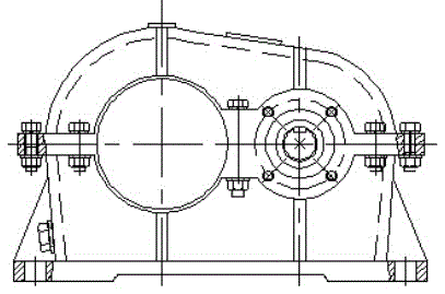
[0051] Such as Figures 1A to 1G As shown, the ring-type speed reducer with backstop function in this embodiment includes upper and lower housings, and the upper and lower housings form cavities for accommodating relevant parts therein.

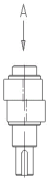
[0052] The eccentric shaft 3 is installed on the two side walls of the lower housing through bearings, and one end extends out of the housing to connect with the driving device to receive input torque, and the end of the other end is sealed by the end cover 2 of the eccentric shaft. Each eccentric shaft 3 is provided with a central shaft and two eccentric wheels uniformly distributed along the circumferential direction of the axis (that is, symmetrically arranged on both sides of the axis of the eccentric shaft, such as Figure 1C and Figure 1D ), each eccentric wheel is integrally formed with the central shaft.

[0053] The output shaft 1 is installed on the two side walls of the lower hou...

Embodiment 2

[0058] Embodiment 2 (one shaft and three rings):

[0059] Such as Figure 2A to Figure 2E As shown, the difference from Embodiment 1 is that there are three eccentric wheels in this embodiment, and the difference between each eccentric wheel is 120 degrees (that is, the plane formed by the axis of each eccentric wheel and the axis of the eccentric shaft is 120 degrees), and the two eccentric wheels 14 and The central shaft is integrally formed (such as Figure 2C ), the other eccentric wheel 13 consists of an independent eccentric wheel (such as Figure 2B ) formed by pinning to the central shaft. There are also three inner tooth plates, and the eccentric wheels corresponding to the positions of the eccentric shafts are respectively accommodated in the through holes of the same inner tooth plate. This structure can also realize the functions of deceleration output and backstop, and compared with the two-ring structure, the operation is smoother. After installation, there i...

Embodiment 3

[0060] Embodiment 3 (one shaft and four rings):

[0061] Such as Figure 3A to Figure 3C As shown, the difference from Embodiment 1 is that there are four eccentric wheels in this embodiment, and the difference between each adjacent eccentric wheel is 90 degrees (that is, the angle between the surfaces formed by the axes of each adjacent eccentric wheel and the axis of the eccentric shaft is 90° degree), wherein the two eccentric wheels 24 are integrally formed with the central shaft (such as Figure 3B ), the other two eccentric wheels 23 are formed by independent eccentric wheels fixed to the central shaft by pins. There are also four inner tooth plates, and the eccentric wheels corresponding to the positions of the eccentric shafts are respectively accommodated in the through holes of the same inner tooth plate. After installation, there is a 180-degree difference between the meshing points of each inner ring gear and the outer gear. This structure can also realize the f...


PUM


Abstract

The invention discloses an annular speed reduction device with a non-return function. The annular speed reduction device comprises an eccentric shaft, N inner-toothed ring plates and an output shaft, wherein the eccentric shaft is provided with a central shaft and N eccentric wheels circumferentially and evenly distributed along the axis, each inner-toothed ring plate is provided with an inner-toothed ring and a through hole matched with the corresponding eccentric wheel so that the eccentric wheel can rotate in the through hole in a sliding friction mode, and the output shaft is provided with outer-toothed wheels meshed with all the inner-toothed rings so that a small-tooth-difference planetary transmission can be formed. When N is two, the angle between every two adjacent eccentric wheels on the eccentric shaft is 180 degrees, and the angle between every two meshing points of the inner-toothed rings and the outer-toothed wheels is also 180 degrees; when N is three, the angle between every two adjacent eccentric wheels on the eccentric shaft is 120 degrees, and the angle between every two meshing points of the inner-toothed rings and the outer-toothed wheels is also 120 degrees; when N is four, the angle between every two adjacent eccentric wheels on the eccentric shaft is 90 degrees, and the angle between every two adjacent meshing points of the inner-toothed rings and the outer-toothed wheels is also 90 degrees. The number of eccentric shafts can be two or three, the number of through holes in each inner-toothed ring plate can be two or three, and the angle between every two adjacent through holes can be 180 or 120 degrees.

Description

technical field [0001] The invention relates to the field of mechanical transmission, in particular to a deceleration backstop device in the mechanical transmission. Background technique [0002] In the existing mechanical transmission system, a reducer or a reduction device is often used to change the output speed of the driving device (such as a motor) to the number of revolutions required by the working machine or an actuator. That is, the front end of the input end of the reducer is the driving device, the output end of the reducer is connected to the input end of the working machine or the actuator, and there are also corresponding brakes or braking mechanisms, generally including couplings, brakes, reducers, etc. The coupling, brake, and reducer described above function independently as a plurality of unit components during operation. When the drive device stops torque input, the brakes are used to brake the rotating components. There are many unit components in the e...

Claims


Application Information

Patent Timeline
Patent Type & Authority Applications(China)
IPC IPC(8): F16H37/02F16H57/021F16H57/023
CPCF16H37/02F16H57/021F16H57/023
Inventor 滕建平姚聒红
Owner HUNAN TECHUAN HEAVY IND TECH CO LTD
Why Eureka
Try Eureka