Backstop, motor device, curtain control device and electric curtain

A backstop and backstop technology, applied in clutches, transmission boxes, mechanical equipment, etc., can solve the problems of poor durability and complex structure of the backstop, and achieve the effect of simple internal structure and less failure.

Pending Publication Date: 2021-05-28
NINGBO SCI FULL MOTOR CO LTD
View PDF0 Cites 1 Cited by
  • Summary
  • Abstract
  • Description
  • Claims
  • Application Information

AI Technical Summary

Problems solved by technology

[0004] Therefore, the embodiment of the present invention provides a backstop, a motor device, a curtain control device and an electric curtain, which can effectively solve the problems of complex structure and poor durability of the existing backstop

Method used


Image

  • Backstop, motor device, curtain control device and electric curtain
  • Backstop, motor device, curtain control device and electric curtain
  • Backstop, motor device, curtain control device and electric curtain

Examples


no. 1 example

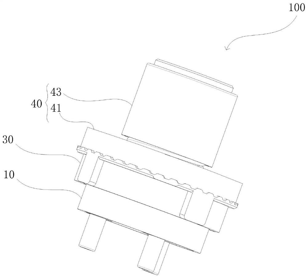
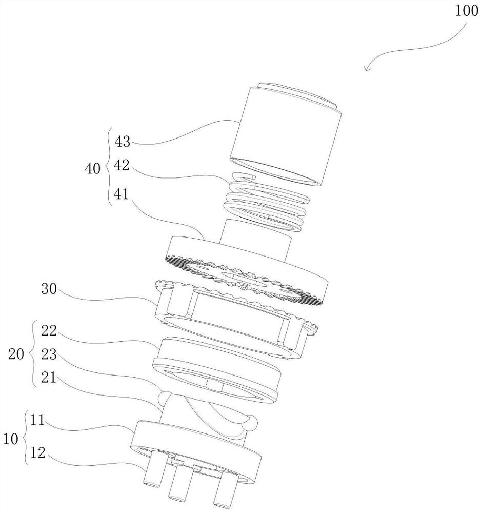
[0039] see figure 1 and figure 2 , which is a structural schematic diagram of a backstop 100 provided in the first embodiment of the present invention. The backstop 100 includes, for example, a driving force receiving part 10 , a control part 20 , a fixing sleeve 30 and a driving force output part 40 . The control unit 20 is disposed on one side of the driving force receiving unit 10 , and the driving force output unit 40 is co-located with the control unit 20 on a side away from the driving force receiving unit 10 .

[0040] Specifically, the driving force receiving part 10 includes, for example: an installation platform 11 and a driving force receiving part 12 . Wherein, the installation platform 11 is connected to the control unit 20; the driving force receiving member 12 is disposed on the side of the installation platform 11 away from the control unit 20, and is used for connecting the motor drive shaft.

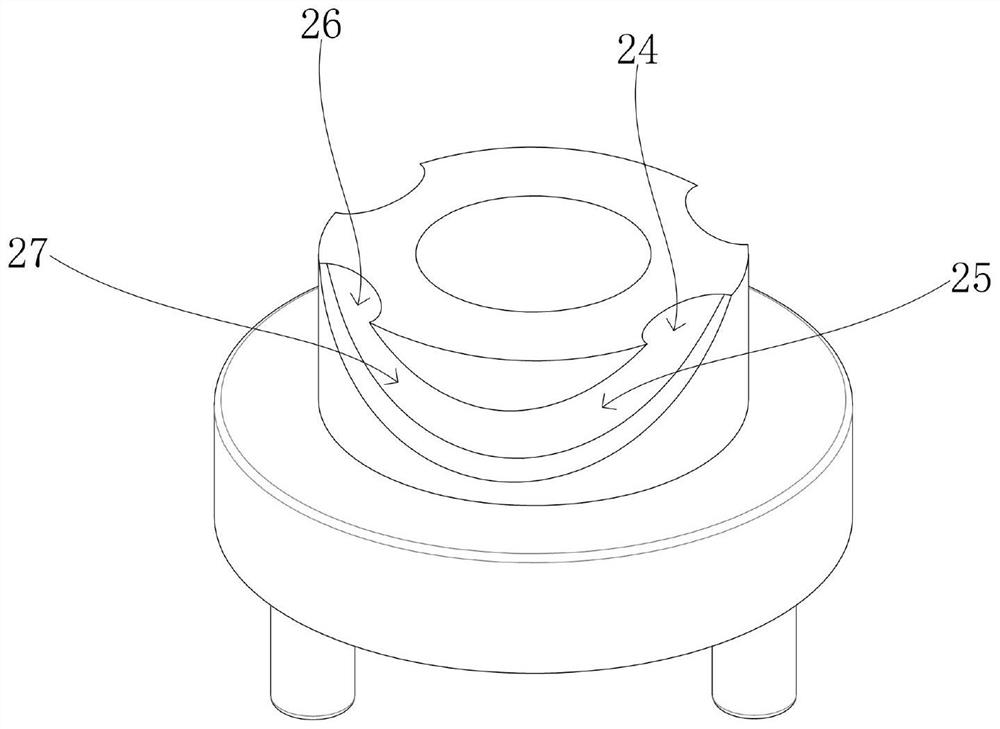
[0041] Specifically, see figure 2 , the control unit 20 inclu...

no. 2 example

[0052] see Figure 9 , which is a schematic structural diagram of a motor device 200 provided in the second embodiment of the present invention. The motor device 200 includes, for example: the backstop 100 as described in the first embodiment and the motor body 210 connected to the backstop 100 .

[0053] Specifically, the motor body 210 has a driving shaft 211 for outputting driving force, and the driving shaft 211 is connected to the driving force receiving portion 10 of the backstop 100 . For example, the driving force receiving part 11 provided on the driving force receiving part 10 is a connecting shaft hole, and the driving shaft 211 is inserted into the connecting shaft hole, so that the motor body 210 can output the forward or reverse driving force to the driving force. Receiver 10.

[0054] For example, the driving force output portion 40 of the backstop 100 may also be provided with an output connection position (not shown in the figure), and the output connection ...

no. 3 example

[0057] see Figure 10 , which is a schematic structural diagram of a curtain control device 300 provided in the third embodiment of the present invention. The curtain control device 300 includes, for example, the motor device 200 and the drum assembly 310 as described in the second embodiment. The motor device 200 is placed inside the reel assembly 310 , and when the motor device 200 rotates, it will drive the reel assembly 310 to rotate.

[0058] Preferably, the reel assembly 310 includes: a reel 311, a first installation position 312, a second installation position 313, and a transmission wheel 314; further, the motor device 200 is provided with a motor body 210 at one end and an output shaft 220 at the other end; Wherein, the motor body 210 is connected to the second installation position 313 , and the output shaft 220 is connected to the transmission wheel 314 .

[0059] Preferably, the first installation position 312 is an installation cylinder, and the installation cyli...


PUM


Abstract

The embodiment of the invention discloses a backstop, a motor device, a curtain control device and an electric curtain. The backstop includes: a driving force receiving part; a control part arranged on one side of the driving force receiving part; a fixing sleeve arranged on the outer side of the control part in a sleeving mode, wherein a first non-return face is arranged on the side, away from the driving force receiving part, of the fixing sleeve; and a driving force output part which is arranged on the side away from the driving force receiving part in the mode of being matched with the control part, and is provided with a second non-return surface which is elastically controlled; the second non-return surface is in an elastic stretching state, and the first non-return surface is matched with the second non-return surface in a non-return manner; and when the driving force receiving part obtains torque, the control part is driven to cooperate with the driving force output part, so that the second non-return surface is in an elastic compression state, the second non-return surface is separated from the first non-return surface, and the driving force output part can rotate. Through the embodiment of the invention, the problems that an existing backstop is complex in structure and poor in durability are effectively solved.

Description

technical field [0001] The invention relates to the technical field of curtain control, in particular to a backstop, a motor device, a curtain control device and an electric curtain. Background technique [0002] As a basic component in mechatronic mechanical transmission, the backstop usually adopts a one-to-one matching arrangement of multiple needle rollers and multiple elastic parts to realize the backstop function. Existing electric curtains include opening and closing type curtains and roller blinds, wherein the roller blinds need a backstop to stop due to the gravity of the roller blinds, so as to prevent the roller blinds from sliding down automatically. [0003] However, the structure of the backstop, which adopts a one-to-one correspondence between a plurality of needle rollers and a plurality of elastic members to realize the backstop function, is complex, prone to failure, and poor in durability. Contents of the invention [0004] Therefore, the embodiment of ...

Claims


Application Information

Patent Timeline
Patent Type & Authority Applications(China)
IPC IPC(8): F16D41/064F16H57/02A47H5/02
CPCF16D41/064F16H57/02A47H5/02
Inventor 周永强谭宝国
Owner NINGBO SCI FULL MOTOR CO LTD
Why Eureka
Try Eureka