Internet of Things signal state indicating circuit of Internet of Things home appliance

A technology for indicating circuit and signal status, applied in electrical components, data exchange networks, home automation networks, etc., can solve problems such as difficult to completely filter out clutter, large error in IoT signal status indication, inaccurate IoT signal detection, etc.

Inactive Publication Date: 2018-04-20
HUANGHE S & T COLLEGE +1
View PDF4 Cites 7 Cited by
  • Summary
  • Abstract
  • Description
  • Claims
  • Application Information

AI Technical Summary

Problems solved by technology

[0004] In view of the above situation, in order to overcome the defects of the prior art, the purpose of the present invention is to provide the signal state indication circuit of the Internet of Things household appliances, which has the characteristics of ingenious design and humanized design, and effectively solves the problem of the Internet of Things due to the Internet of Things household appliances. The clutter of the signal is difficult to completely filter out and the frequency of the abnormal signal is relatively close to that of the normal signal, which leads to inaccurate detection of the IoT signal of the IoT home appliance, and a large error in the status indication of the IoT signal of the IoT home appliance.

Method used


Image

  • Internet of Things signal state indicating circuit of Internet of Things home appliance
  • Internet of Things signal state indicating circuit of Internet of Things home appliance

Examples


Embodiment 1

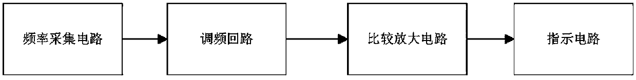
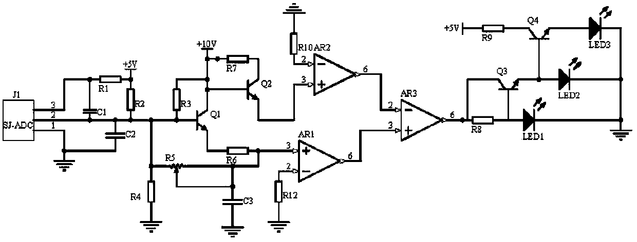
[0014] Embodiment 1, the signal state indication circuit of the Internet of Things household appliances includes a frequency acquisition circuit, a frequency modulation circuit, a comparison amplifier circuit and an indication circuit, and the frequency acquisition circuit collects the frequency of the Internet of Things signal of the Internet of Things household appliances when using the Internet of Things, The frequency modulation circuit uses transistors Q1, Q2, capacitor C3 and adjustable resistor R5 to form a composite circuit for frequency selection of the frequency signal, and filters out the clutter in the frequency signal. The output of the frequency modulation circuit can be adjusted by adjusting the resistance of the adjustable resistor R5 The potential size of the signal, the output signal of the frequency modulation circuit is compared and amplified by the comparison and amplification circuit, and the op-amp AR1 and AR2 are respectively input into the non-inverting ...

Embodiment 2

[0016] Embodiment 2. On the basis of Embodiment 1, the frequency acquisition circuit selects the frequency collector J1 of the model SJ-ADC to collect the frequency of the Internet of Things signal when the Internet of Things home appliance is used and outputs an analog potential signal. Capacitor C2 It is a filter capacitor, the power supply terminal of the frequency collector J1 is connected to one end of the resistor R1 and one end of the capacitor C1, the other end of the resistor R1 is connected to the power supply +5V and one end of the resistor R2, and the output terminal of the frequency collector J1 is connected to capacitors C1 and C2 One terminal and one terminal of the resistor R2, and the base of the transistor Q1, the ground terminal of the frequency collector J1 and the other terminal of the capacitor C2 are grounded.

Embodiment 3

[0017]Embodiment 3. On the basis of Embodiment 1, the indication circuit uses triodes Q3 and Q4 to form a step-by-step conduction circuit. When the signal input by the frequency acquisition circuit is between +8V-+10V, the triodes Q3 and Q4 are both When it is turned on, the indicators LED1-LED3 are all on at this time, which means that the IoT signal needs to be repaired and the IoT home appliance needs to be shut down immediately when the IoT appliance is in use, which is a three-level alarm; when the signal input by the frequency acquisition circuit is at +7V When between -+8V, the triode Q3 is turned on, and the indicators LED1 and LED2 are on at this time, which means that the IoT signal of the IoT home appliance needs to be repaired when the IoT is in use, and the IoT home appliance does not need to be turned off, which is a secondary alarm; when the frequency is collected When the signal input by the circuit is between +5V-+7V, the indicator LED1 is on at this time, whic...


PUM


Abstract

The invention discloses an Internet of Things signal state indicating circuit of an Internet of Things home appliance. The Internet of Things signal state indicating circuit comprises a frequency collection circuit, a frequency modulation loop, a comparison and amplification circuit and an indicating circuit, the frequency collection circuit collects the frequency of an Internet of Things signal when the Internet of Things of the Internet of Things home appliance is used, the frequency modulation loop performs composite circuit frequency selection on a frequency signal by using triodes Q1, Q2,a capacitor C3 and an adjustable resistor R5, the size of level of an output signal of the frequency modulation loop can be adjusted by adjusting the resistance of the adjustable resistor R5, the output signal of the frequency modulation loop is separately input to an in-phase input end and an inverting input end of an operational amplifier AR3 by the comparison and amplification circuit by usingoperational amplifiers AR1 and AR2 for comparison and amplification, the output signal of the comparison and amplification circuit is used as a driving signal of the indicating circuit to control thelevel-by-level conduction of triodes Q3 and Q4, when the Internet of Things function of the Internet of Things home appliance is used, the condition of the Internet of Things signal is judged throughthe number of turned on indicator lamps LED1 to LED3, and the effect of detecting the Internet of Things function of the Internet of Things home appliance in real time is achieved.

Description

technical field [0001] The present invention relates to the technical field of signal state indication circuit of the Internet of Things, in particular to the signal state indication circuit of the Internet of Things for home appliances of the Internet of Things. Background technique [0002] With the advancement of science and technology, home appliances of the Internet of Things have gradually entered people's lives. Based on the Internet of Things, the topology structure is extended to control corresponding home appliances, such as indoor lights, refrigerators, TVs, and air conditioners. The composition is based on the Internet of Things. The smart home system has greatly improved people's quality of life. If the Internet of Things signal is abnormal, home appliances will not be controlled, which will bring great changes to people's lives, and may even bring unpredictable Therefore, it is necessary to detect the IoT function of the IoT home appliance in real time, and i...

Claims


Application Information

Patent Timeline
Patent Type & Authority Applications(China)
IPC IPC(8): H04L12/28H04L12/26H04B1/16
CPCH04B1/16H04L12/2803H04L12/2823H04L43/0817
Inventor 王学春杨阿平姜维
Owner HUANGHE S & T COLLEGE
Why Eureka
Try Eureka